Control & Communications
36 Siemens Energy & Automation, Inc.
6.8 Breaker Operations Count
Breaker Operations refers to the number of times the device
has opened the breaker. The Breaker Operation function
allows the setting of the breaker monitoring parameters.
The Sum of Interrupted Current is the total sum of the cur-
rents that were interrupted by these breaker openings. The
setpoint is triggered when any phase exceeds the set limit.
The Interrupted I (current) Function (3501) can be enabled or
disabled. When enabled, the function generates an event
(which can be matrixed to an output contact) when the inter-
rupted current exceeds the pickup value. The interrupted
current pickup value (3502) can be set to any value from 0 to
9999.90 kA in steps of 0.01 kA.
The Breaker Operations Function (3503) can be enabled or
disabled. When enabled, the function counts the breaker
operations since the last reset.
The Breaker Operations Counter (3504) can be set from 0 to
65535.
6.9 Hardware Status (Relay Data)
The Relay Data function provides additional hardware infor-
mation on the ISGS relay, shows all set binary inputs and
outputs, and displays a relay identification string.
3500 Breaker Operation
Address Parameter Selection
3501 Int. I Function Enabled or Disabled
3502 Int. I Pickup 0-9999.90 kA
(0.01 kA steps)
3503 Brks Ops Function Disabled or Enabled
3504 Brks Ops Counter 0-65535
7400 Relay Data
Address Data Description
7401 Circuit Name String of up to 16 characters
7402 MainBd S/N Serial number of main board
7403 MainBd ID ID number of main board
7404 OptBd1 S/N Serial number of option board 1
7405 OptBd1 ID ID number of option board 1
7406 OptBd2 S/N Serial number of option board 2
7407 OptBd2 ID ID number of option board 2
7408 Bin. Inputs Binary input status
7409 Bin. Outputs Output contact status
The Circuit Name (7401) identifies a relay, breaker, bus, or
feeder which your ISGS relay is protecting. This string (up to
16 characters) is user-definable with Wisdom software.
Accessing this parameter through the keypad allows only the
display of this string.
All circuit boards installed in your ISGS relay are provided
with a serial number and a special identification number.
These numbers can be displayed by accessing addresses
7403 to 7407.
Similar to the firmware version identification number of your
ISGS relay described in Section 4.1, the serial and identifi-
cation numbers of your main board and optional board(s)
help Siemens track the versions and options available on
your boards.
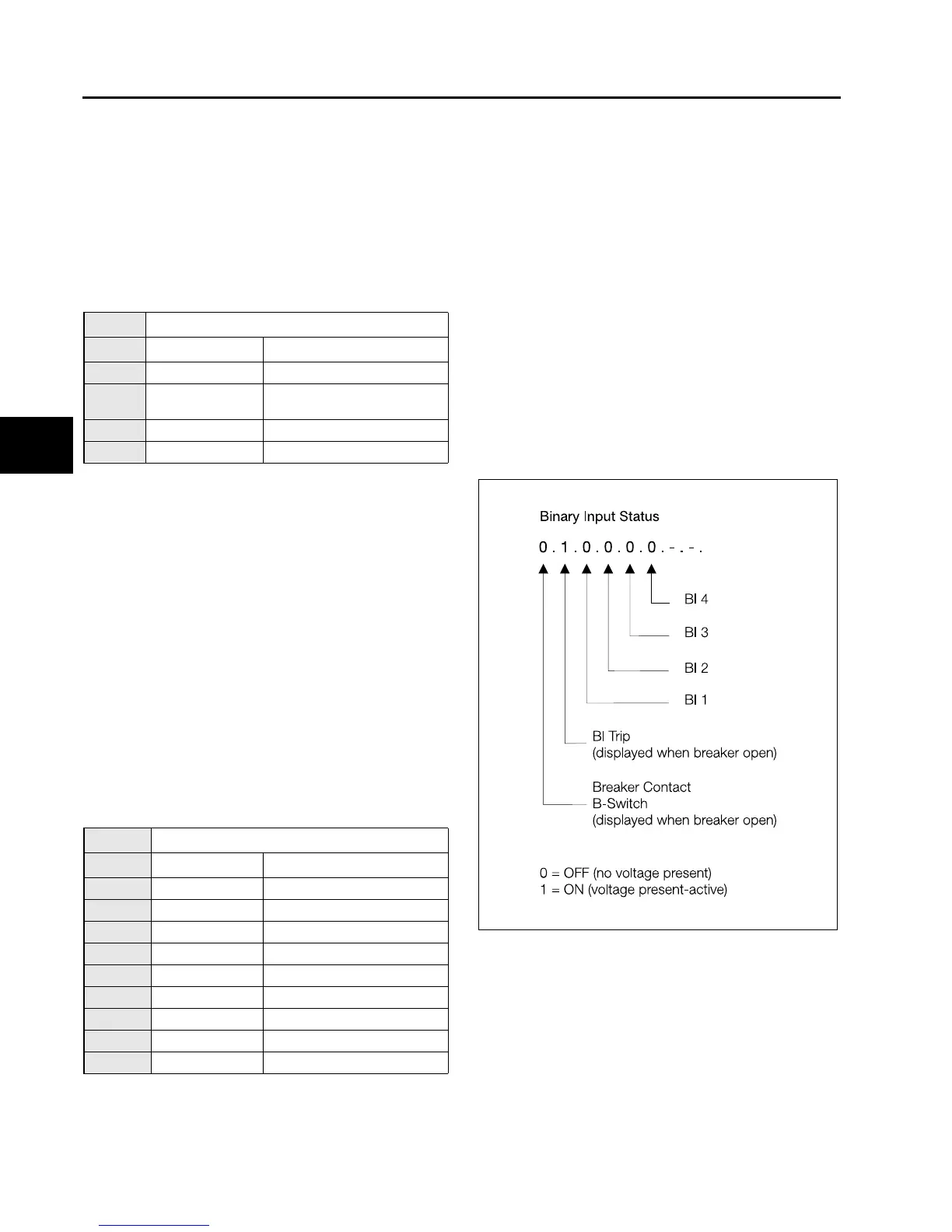
Binary Inputs (7408) displays the status of the binary inputs
as illustrated in Figure 6.2. The status updates automatically
as they change.
Figure 6.2 Binary Input Status
6
isv3o_1.bk : isv3oc&c.frm Page 36 Wednesday, August 7, 1996 10:51 AM
 Loading...