Appendix E: Schematics
80 Siemens Energy & Automation, Inc.
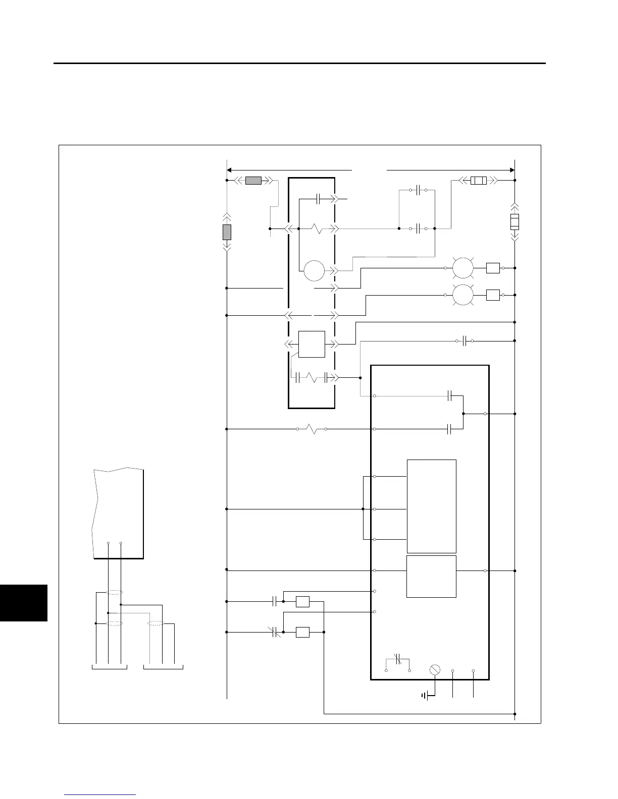
E.2 AC (Capacitor) Trip Systems
The following diagram illustrates a typical connection
scheme for the ISGS relay when using an AC trip system.
Figure E.2 Wiring for AC (Capacitor) Trip System
52
SRC
LS
88
52T
52a
52a
52b52a
313 16 1114
15 214
AC0
AC1
3
1
4
2
3
1
4
2
Slug
1-Fuse
Slug
1-Fuse
RES
RES
RES
RES
RG
3
4
CS
C
95C
1
2
CS
T
52
1516 12
20
19
49
49
48
48
14211
1
17 18
13
Trip
Common
Trip 1 Trip 2
BI
Trip
PS
IN2
PS
IN1
BI
BSW
Trip Source
Impedance
Sense Circuit*
Power
Supply
(AC-DC)
*Contact is
closed when
relay is out of service
95C
Optional
Remote
Closing
Relay
Disabled*
Optional
RS-485
Communications
Optional
RS-485
Communications
Outgoing
RS-485
Bus
Incoming
RS-485
Bus
+
-
(see below)
Case
Ground
Data + Data +
Data +
Data - Data -
Data -
Shield
Shield
Key
52a
Aux Switch (open when breaker is open)
52b
Aux Switch (closed when breaker is open)
52T
Opening Solenoid (Trip)
52SRC
Spring Release Solenoid
88
Spring Charging Motor
CS/C
Control Switch/Close
CS/T
Control Switch/Trip
R
Red Lamp (breaker open)
G
Green Lamp (breaker open)
95C
Interposing Relay
CTD
Capacitor Trip Device
LS
???
AC Supply
(120 VAC
Only)
CTD
*Not used with AC configuration.
Tie impedance source (terminal 17),
ground monitor (16), and impedance
sense (18) to AC0.
Breaker
ISGS Relay
E
isv3o_1.bk : isv3osch.frm Page 80 Wednesday, August 7, 1996 10:51 AM
 Loading...