Control & Communications
Siemens Energy & Automation, Inc. 37
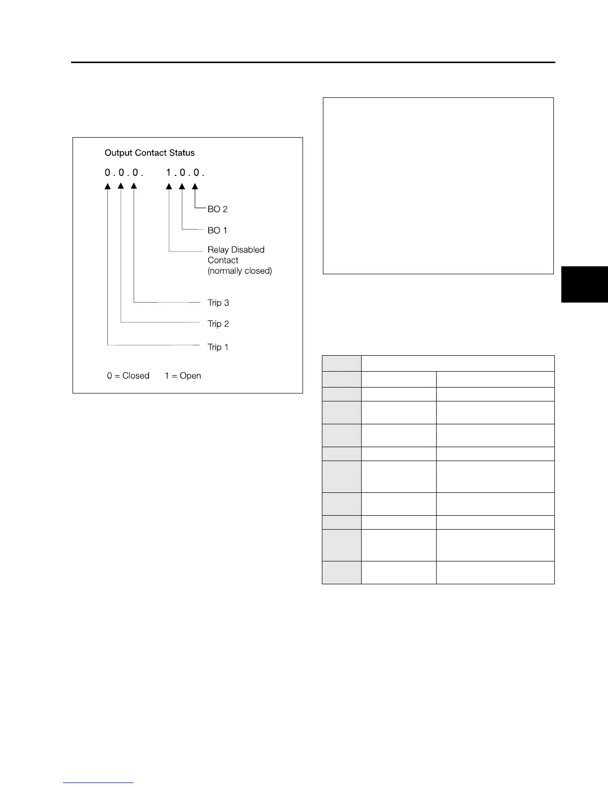
Binary Outputs (7409) displays the output contact status as
illustrated in Figure 6.3. The status updates automatically as
they change.
Figure 6.3 Output Contact Status
6.10 Self-Monitoring (Value Supervision)
Value supervision refers to the relays ability to monitor its
own input and measurement functions for problems. The
complete chain, from input transformers up to and including
the A/D converter internal to the ISGS, is monitored by a
plausibility check on the measured values. These checks
consist of voltage balance checks, current balance checks,
and current summation checks.
Voltage or current balance checks can be performed to
detect open or short circuits in the external transformers and
their connections. Current summation checks are performed
on the instantaneous samples of the A/D converter.
A useful application of the current and voltage balance and
monitoring functions is the detection of blown VT fuses. A
blown fuse condition can be said to exist when the following
conditions are present:
Voltage is present but unbalanced,
AND
current is present but NOT unbalanced.
Therefore, a voltage balance alarm in the absence of a cur-
rent unbalance alarm is a good indication that a fuse is
blown. If a current unbalance alarm were also active, it would
indicate the presence of negative sequence current and
therefore a fault rather than a blown VT fuse.
Voltage Balance
The Voltage Balance function can be enabled or disabled
(3401). When enabled, the function monitors the phase volt-
ages to see if they are approximately balanced (of equal
magnitude). Balance is defined as the ratio of minimum to
maximum voltage, where the maximum voltage is the largest
and the minimum voltage the smallest of the three voltages
determined by the way the relay is connected (line-to-line or
line-to-neutral).
3400 Value Supervision
Address Parameter Selection
3401 Function V Bal Enabled or Disabled
3402 Pickup V Bal 40-120 V (0.1 V steps)
(default is 100)
3404 Factor V Bal 0.58-0.95 (0.01 steps)
(default is 0.8)
3411 Function I Sum Enabled or Disabled
3412 Pickup I Sum 5 A CTs: 0.5-5 A
1 A CTs: 0.1-1 A
(0.1 A steps)
3414 Factor I Sum 0.10-0.95 (0.01 steps)
(default is 0.1)
3421 Function I Bal Enabled or Disabled
3422 Pickup I Bal 5 A CTs: 0.5-5 A
1 A CTs: 0.1-1 A
(0.1 A steps)
3424 Factor I Bal 0.10-0.95 (0.01 steps)
(default is 0.8)
V
1
25 V>
AND V
2
0.33 V
1
AND I
2
0.167 I
1
<
OR I
1
0.1 I
N
<
<
where V
1
= positive sequence voltage
I
2
= negative sequence current
I
1
= positive sequence current
I
N
= nominal current (1 or 5 A)
6
isv3o_1.bk : isv3oc&c.frm Page 37 Wednesday, August 7, 1996 10:51 AM
 Loading...