Migration from MC35 to MC35i
PRELIMINARY
Migration from MC35 to MC35i
10 of 30 12.03.03
4.2 Operating modes
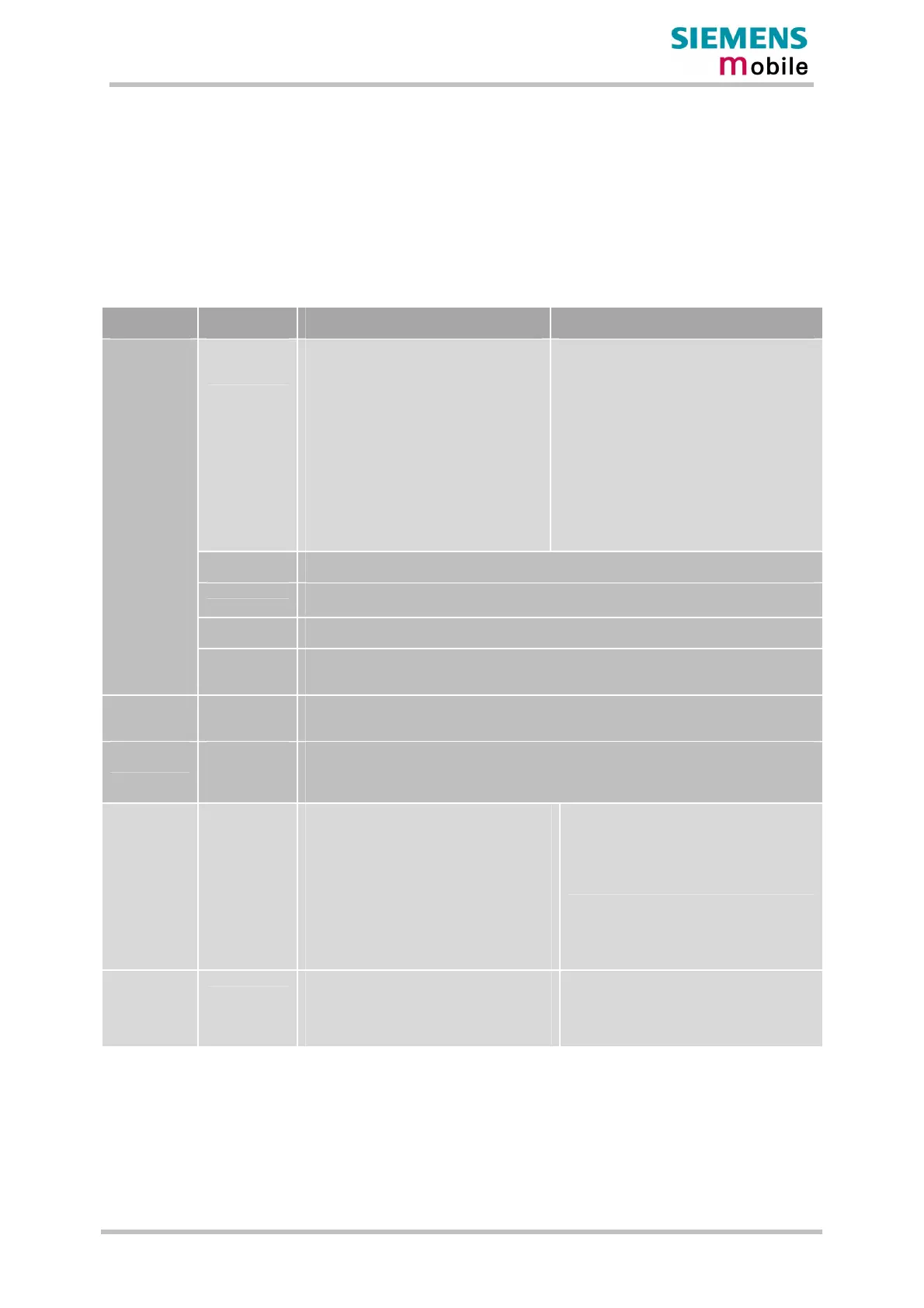
The operating modes for MC35 and MC35i modules are listed in the table below.
The MC35i module supports two additional sleep modes compared to MC35. For
further details please consult the MC35i manual.
The table below shows operating modes overview for both devices.
Table 3: Operating modes
Mode Function MC35 MC35i
GSM / GPRS
SLEEP
Power-save modes set with AT+CFUN
command.
Software is active to minimum extent. If
the module was registered to the GSM
network in IDLE mode, it is registered and
paging with the BTS in SLEEP mode, too.
Power saving can be chosen at different
levels: The
NON-CYCLIC SLEEP mode (AT+CFUN=0)
disables the AT interface. The two CYCLIC
SLEEP modes AT+CFUN=5 or 6 alternate
activating and deactivating the AT
interface to allow permanent access to all
AT commands.
Software is active to a minimum extent. If the
module was registered to a GSM network in
IDLE mode, it remains, in SLEEP mode,
registered and pageable from the BTS.
Power saving can be chosen at different
levels. The NON_CYCLIC SLEEP mode
(AT+CFUN=0) disables the AT interface. The
CYCLIC SLEEP mode AT+CFUN=5, 6, 7
and 8 alternatingly activate and deactivate
the AT interface to allow permanent access to
all AT commands.
GSM IDLE
Software is active. Once registered to the GSM network, paging with BTS is carried out. The
module is ready to send and receive.
GSM TALK Connection between two subscribers is in progress. Power consumption depends on network
coverage individual settings, such as DTX off/on, FR/EFR/HR, hopping sequences, antenna.
GPRS IDLE
Module is ready for GPRS data transfer, but no data is currently sent or received. Power
consumption depends on network settings and GPRS configuration (e.g. multislot settings).
Normal
operation
GPRS DATA
GPRS data transfer in progress. Power consumption depends on network settings (e.g.
power control level), uplink / downlink data rates and GPRS configuration (e.g. used
multislot settings).
POWER
DOWN
Operating voltage is applied. Only a voltage regulator in the Power Supply ASIC is active for
powering the RTC. Software is not active. The serial interface is not accessible.
Alarm mode
Restricted operation launched by RTC alert function while the module is in Power Down
mode. Module will not be registered to GSM network. Limited number of AT commands is
accessible. If application is battery powered: No charging functionality in Alarm mode
(MC35 only)
Charge-only
mode
Limited operation for battery powered
applications. Enables charging while engine
is detached from GSM network. Limited
number of AT commands is accessible.
There are several ways to launch Charge-
only mode:
æ From Power Down mode: Connect
charger to POWER lines when engine was
powered down by AT^SMSO.
æ From Normal mode: Connect charger
to POWER lines, then enter AT^SMSO
Not supported
Charge mode
during normal
operation
Normal operation (SLEEP, IDLE, TALK, GPRS
IDLE, GPRS, DATA) and charging running in
parallel. Charge mode changes to Charge-
only mode when the module is powered
down before charging has been completed.
Not supported
 Loading...