English 6. SYSTEM PARAMETERS
Parameter Function Range
[Default]
Description / Notes
G85139-H1751-U529-D1 © Siemens plc 199
4/8/99
42
P000
Operating display -
This displays the output selected in P001.
In the event of a failure, the relevant fault code (Fnnn) is displayed (see
section 7) or the display flashes in the event of a warning (see P931) or If
output frequency has been selected (P001 = 0) and the inverter is in stand-by
mode, the display alternates between the setpoint frequency and the actual
output frequency which is zero Hz.
P001 ·
Display mode 0 - 9
[0]
Display selection:
0 = Output frequency (Hz)
1 = Frequency setpoint (i.e. speed at which inverter is set to run)
(Hz)
2 = Motor current (A)
3 = DC-link voltage (V)
4 = Motor torque (% nominal)
5 = Motor speed (rpm)
6 = USS serial bus status (see section 9.2)
7 = PID Feedback signal (%)
8 = Output voltage (V)
9 = Instantaneous rotor / shaft frequency (Hz).Note: Applicable only for
Sensorless Vector control mode.
Notes: 1. The display can be scaled via P010.
2. When the inverter is operating in Sensorless Vector Control
mode (P077 = 3) the display shows actual rotor / shaft speed in
Hz. When the inverter is operating in V/f or FCC modes (P077 = 0,
1 or 2) the display shows inverter output frequency in Hz.
WARNING: In Sensorless Vector Control mode (P077 = 3) the display
shows 50Hz when a 4-pole motor is rotating at 1500rpm
which may be slightly higher than the nominal speed shown
on the motor rating plate.
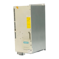
P002 ·
Ramp-up time (seconds)
MMV
MDV550/2, 750/2, 750/3, 1100/3,
220/4, 400/4, 550/4, 750/4, 1100/4.
MDV1100/2, 1500/2, 1850/2, 2200/2,
1500/3, 1850/3, 2200/3, 3000/3,
3700/3, 1500/4, 1850/4, 2200/4,
3000/4, 3700/4.
MDV3000/2, 3700/2, 4500/2, 4500/3,
5500/3, 7500/3.
0 - 650.0
[10.0]
[10.0]
[20.0]
[40.0]
This is the time taken for the motor to accelerate from standstill to the maximum
frequency as set in P013. Setting the Ramp-up time too short can cause the
inverter to trip (fault code F002 - overcurrent).
Frequency
f
max
0 Hz
Time
amp up
time
(0 - 650 s)
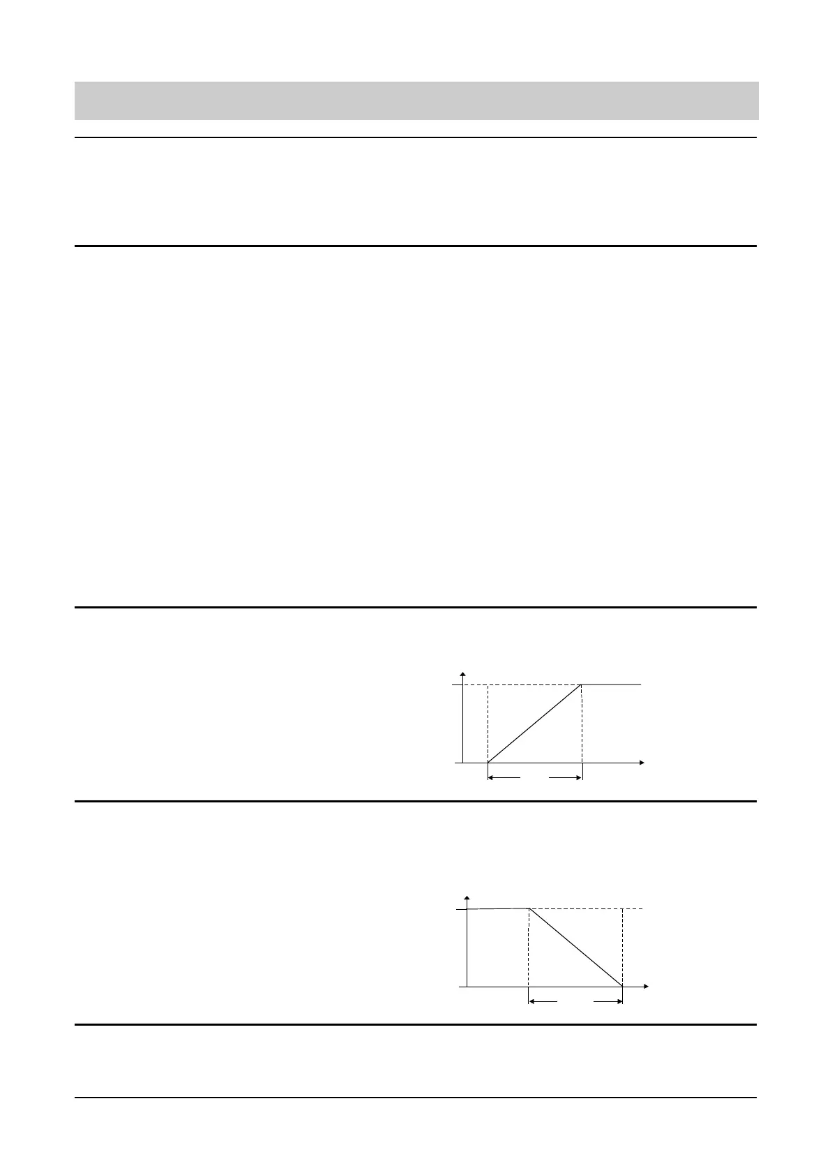
P003 ·
Ramp-down time (seconds)
MMV
MDV550/2, 750/2, 750/3, 1100/3,
220/4, 400/4, 550/4, 750/4, 1100/4.
MDV1100/2, 1500/2, 1850/2, 2200/2,
1500/3, 1850/3, 2200/3, 3000/3,
3700/3, 1500/4, 1850/4, 2200/4,
3000/4, 3700/4.
MDV3000/2, 3700/2, 4500/2, 4500/3,
5500/3, 7500/3.
0 - 650.00
[10.0]
[10.0]
[20.0]
[40.0]
This is the time taken for the motor to decelerate from maximum frequency (P013)
to standstill, Setting the Ramp-down time too short can cause the inverter to trip
(fault code F001 -DC Link overvoltage).
This is also the period for which DC injection braking is applied when P073 is
selected.
Frequency
f
max
0 Hz
Time
amp
own
time
(0 - 650 s)
 Loading...