6
4.3 Setting the Communications Module Jumpers
Prior to installing the Communications Module into the MJ-4 Control Panel, ensure that the jumpers are properly
installed on the printed circuit board. Jumper selections for the Fiber Optic interface and RS232/485 interface are
described in separate sections below.
4.3.1 Fiber Optic Interface
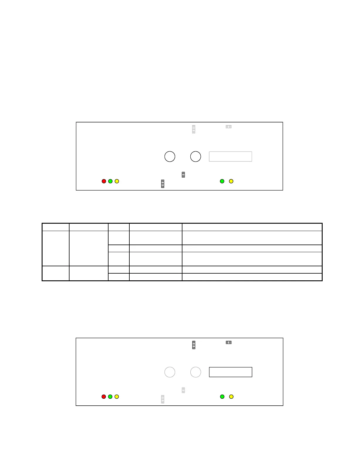
The jumper locations for the fiber optic interface are shown in Figure 4-3. The view of the module is from the
component side. The fiber optic receiver (RX) and transmitter (TX) are shown for reference. The jumper settings
are listed in Table 4-1.
Set Auto Repeat to “No Repeat” when only one unit is installed in the network.
J11
J10
J12
1
2
J14
1
2
3
Figure 4-3 Fiber Optic Interface Jumper Locations.
Table 4-1 Fiber Optic Interface Jumper Settings
Jumper Name Position Function Selected State Description
1-2
Auto Repeat Repeat message from Host and any responses from
other IEDs (Auto repeat for mark 0 or mark 1)
2-3 No Repeat Transmit continuously ON (for testing) (Force 0)
J14 Auto Repeat
Out No Repeat Only transmit a response if being addressed by Host
(no jumper installed at 1-2 or 2-3) (Force 1)
Out
Normal Set Low Power Transmitter Output
J12 Range
In Long Set High Power Transmitter Output (See Note 2)
Note 1: Default pin settings are shown in bold text.
Note 2: If 50/125 µm cable is used, J12 must be jumpered (In).
4.3.2 RS-232/485 Interface
Figure 4-4 shows the jumper locations for the RS-232/485 interface, viewed from the component side. Jumpers and
their default settings are listed in Table 4-2.
1
2
J11
1
2
3
J10
J12
J14
Figure 4-4 RS-232/485 Interface Jumper Locations.
 Loading...


