MJ-4 Communications Module
13
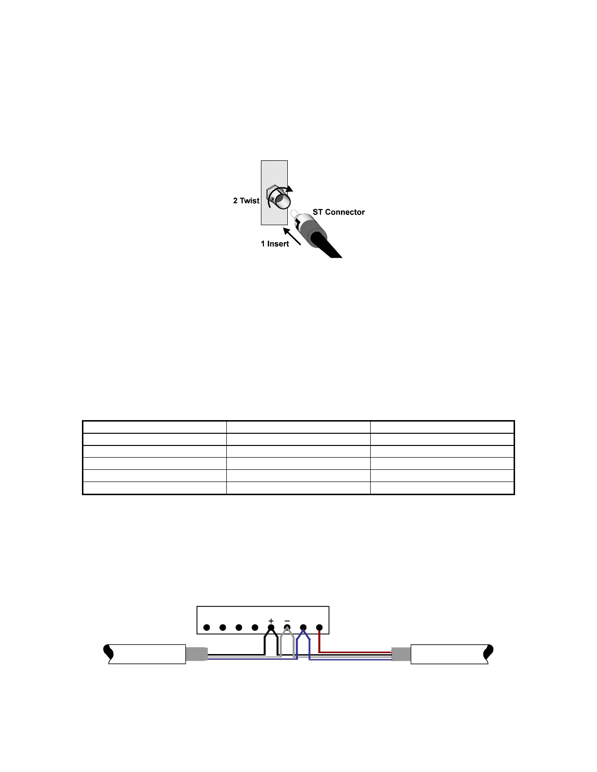
7.1.3 Fiber Optic Connections
When making connections to the transmitter and receiver inputs/outputs, ensure that the transmit output from one
device is connected to the receive input of the next device. Figure 7-1 shows how to insert the connector. The tip of
the cable on the ST connector must be clean and free of dust. Dust on the tip of the cable will cause signal
attenuation.
Use care when handling the fiber optic connector, especially the exposed ceramic ferrule.
Figure 7-1 Fiber Optic Connections
7.2 RS-485 Twisted-pair Cable
The following sections provide the information necessary to select and install cable between an MJ-4 Control Panel,
RTU, and other field devices in an RS-485 network.
7.2.1 RS-485 Cable Type
Listed in Table 7-1 are the cable characteristics necessary for proper electrical performance in an RS-485
communications network. Use cable with a shield that provides 100 percent RFI/EMI coverage.
Table 7-1 RS-485 Cable Specifications
Characteristic Value Maximum/Typical
Impedance 120 ohms Typical
Capacitance (pF/ft) 35 Maximum
Cable Size 22 AWG Typical
DC Resistance 17 ohms/1000 ft Maximum
Velocity of Propagation 80% Maximum
7.2.2 RS-485 Cable Grounding
Ground the cable shield for all devices on the network. Ground the cable shield at only one end to prevent induced
interference that may result from circulating ground currents. If a cable shield is grounded at both ends, a ground
loop can exist between the components. This ground loop can cause induced interferences that result in signal
distortion. If there is a ground potential rise between the connected devices, connect the Signal Return (RTN)
between the communication devices. Figure 7-2 illustrates the preferred field device connection method. See section
4.3.2 for jumper considerations.
Data
GND
RS-485 Twisted-Pair Cable
Shield grounded
At other end only
From RTU or other device
MJ-4 Communications Module
RTN
RS-485 Twisted-Pair Cable
Shield attached
at this end only
To ne xt device
Figure 7-2 RS-485 Connection
 Loading...


