MJ-4 Communications Module
5
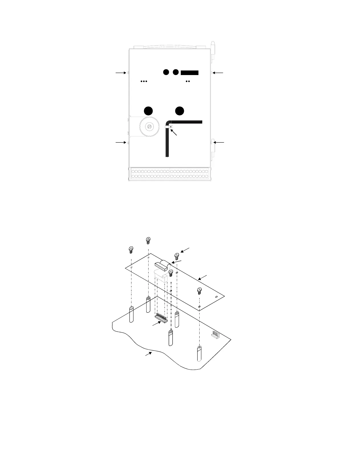
Uncurl cable-clamp
and slide cable out
Remove 4
Case
Screws
Figure 4-1 MJ-4 Rear Cover.
4.2 Mounting the Communications Module
Hold the communications module in place over the five standoffs on the main PCB and insert the 24-pin connector
on the ribbon cable into the 24-pin connector (P8) on the main PCB. See Figure 4-2 below. Mount the
communications module on the threaded standoffs on the main PCB using the five screws provided.
6-32 x 3/8" Screw (5)
Comm Mod PCB
Ribbon Cable with 24-Pin Connector
MJ-XL Main PCB
24-Pin Connector
P8
P9
MJ-4 Main PCB
Figure 4-2 Communications Module Installation.
 Loading...


