Communication Ports
4.3.2Serial RS232/RS485/RS422 RJ45 Ports
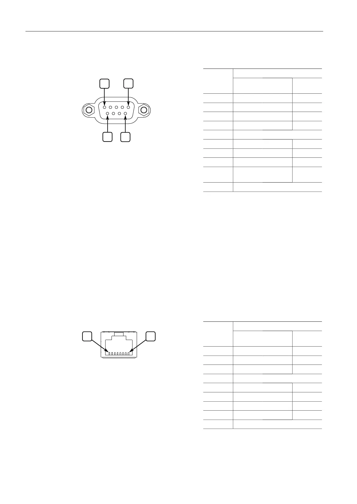
The following is the pin-out description for the RS232/RS485/RS422 DB9 ports:
Figure4.8 RS232/RS485/RS422 DB9
Serial Console Port
NamePin
a
RS232
Mode
RS485
Mode
RS422
Mode
1
b
DCD
2 TX TX/RX+ TX+
3 RX RX+
4
b
DTR
5 Common (Isolated Ground)
c
6
b
DSR RX-
7
d
CTS
e
TX/RX- TX-
8
d
RTS
e
9 RI (No
Connection)
Shield Chassis Ground
a
No internal termination is provided.
b
Connected internally.
c
The Common terminal is isolated. However, there is transient voltage protection circuitry between the
Common terminal and chassis ground.
d
Cnnected internally.
e
In RS232 mode, this pin enters a high impedance state. A DTE that asserts RTS will see CTS asserted,
although the device will not perform hardware flow control.
4.3.2 Serial RS232/RS485/RS422 RJ45 Ports
The RUGGEDCOM RS910 can be equipped with serial RS232/RS485/RS422 RJ45 ports.
Each port can be set individually through the RUGGEDCOM ROS operating system
to operate in RS232, RS485 or RS422 mode. For more information, refer to the
RUGGEDCOM ROS Configuration Manual for the RUGGEDCOM RS910.
The following is the pin-out description for the RS232/RS485/RS422 RJ45 ports:
Figure4.9 RS232/RS485/RS422 RJ45
Serial Console Port
NamePin
a
RS232
Mode
RS485
Mode
RS422
Mode
1
b
DSR/RI RX-
2
b
DCD
3
c
DTR
4 Common (Isolated) Ground
5 RX RX+
6 TX TX/RX+ TX+
7
c
CTS
d
8
c
RTS
d
TX/RX- TX-
Shield Chassis Ground
a
No internal termination is provided.
b
Connected internally.
RUGGEDCOM RS910
Installation Manual, 04/2021, C79000-G8976-1029-12
25
 Loading...