Installation and connecting up
3.2 Installing the CP
CP 1542SP-1, CP 1542SP-1 IRC, CP 1543SP-1
34 Operating Instructions, 01/2017, C79000-G8976-C426-03
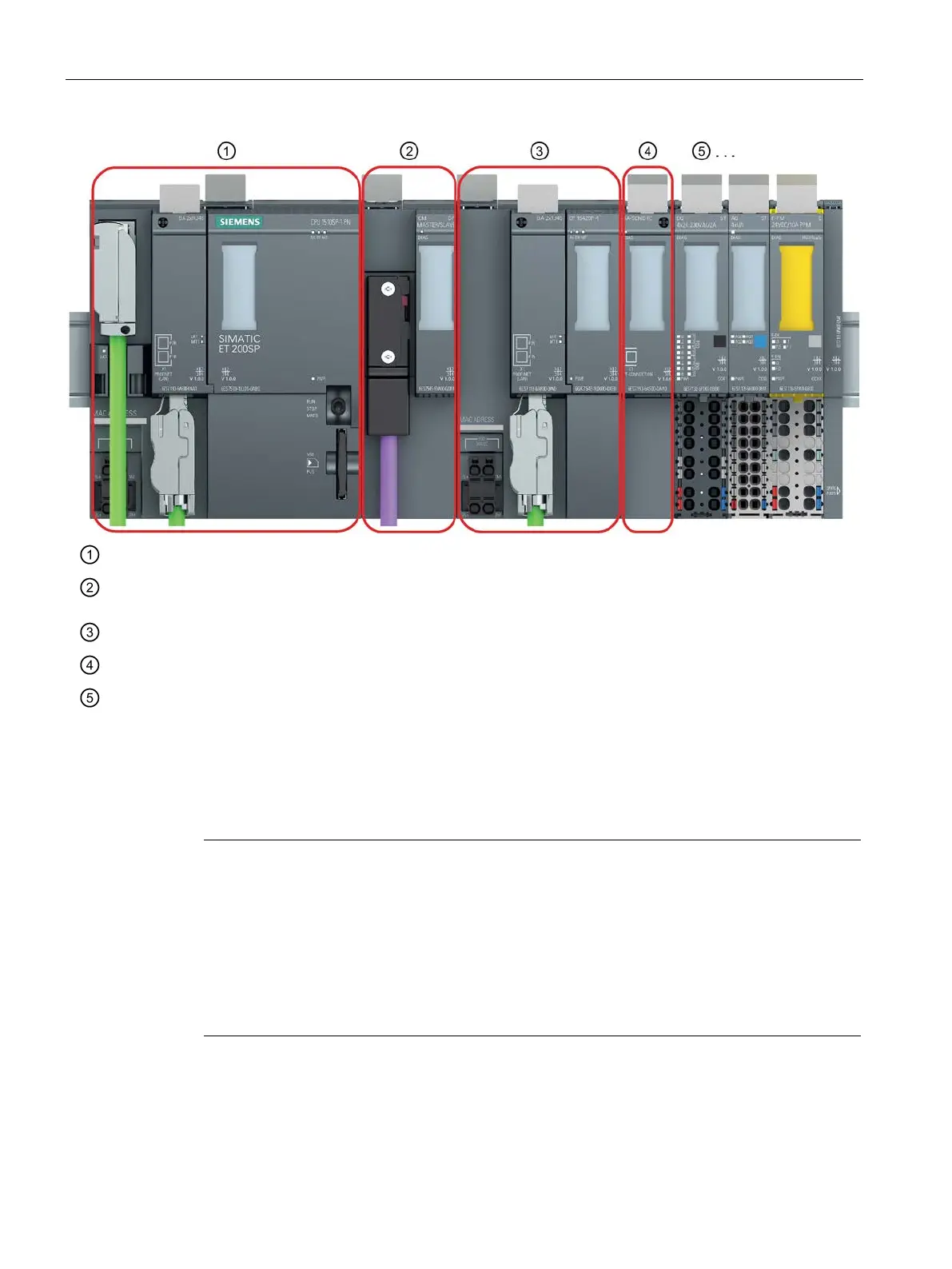
Slot 1 - only permitted for the CPU.
Slot 2 - for CM / CP / BusAdapter Send
If you use a PROFIBUS CM, you must plug this in directly beside the CPU in slot 1.
Slot 3 - for CM / CP / BusAdapter Send
Slot 4 - for CM / CP / BusAdapter Send
Slot 5 ff for IO modules
* If you use a BusAdapter Send, this must be plugged in to the slot directly beside the IO modules.
Figure 3-1 Slots of the ET 200SP
Installation on a DIN rail
Note
Protecting the modules from slipping on the DIN rail
If you insta
ll the modules in an area with mechanical load, use suitable clamping devices at
both ends of the device group to secure the modules on the DIN rail, e.g. Siemens and
retainer 8WA1808.
The end retainers prevent the modules separating under mechanical load.
When using the device in the areas of application ATEX or IECEx, note the information on
the DIN rai in section
Notes on use in hazardous areas (Page 29).
 Loading...