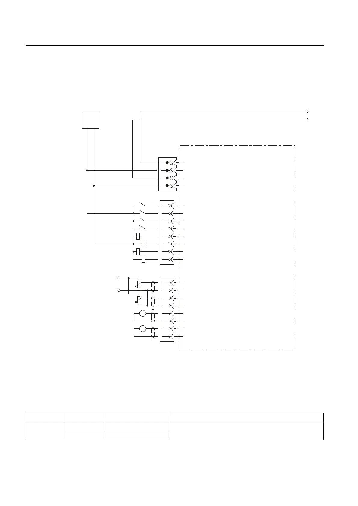
7.3.3.2 Connection diagram
The following figure shows the schematic diagram of the TB30 as well as its connections for
inputs (DI, AI), outputs (DO, AO) and power supply.
'2
'2
'2
'2
',
',
',
',
s
$2
$2
$2
$2
$,
$,
$,
$,
9
9
*
*
*
*
b9
*
*
H[W
9
7%7HUPLQDO%RDUG
;
;
;
Figure 7-5 TB30 connection diagram
7.3.3.3 Power supply of digital outputs
Table 7-3 Terminal block X424
Terminal Function Technical specifications
+ Power supply Voltage: 24 V DC (20.4 V–28.8 V)
Max. power consumption: 4 A
+ Power supply
Supplementary system components
7.3 TB30 terminal board
SIMOTION D4x5
90 Manual, 04/2014

 Loading...


