Description
3.4 Operating and display elements
NCU 7x0.2
Manual, 02/2011, 6FC5397-0AP20-0BA0
27
3.4.5 Start-up and mode selector switch
Layout
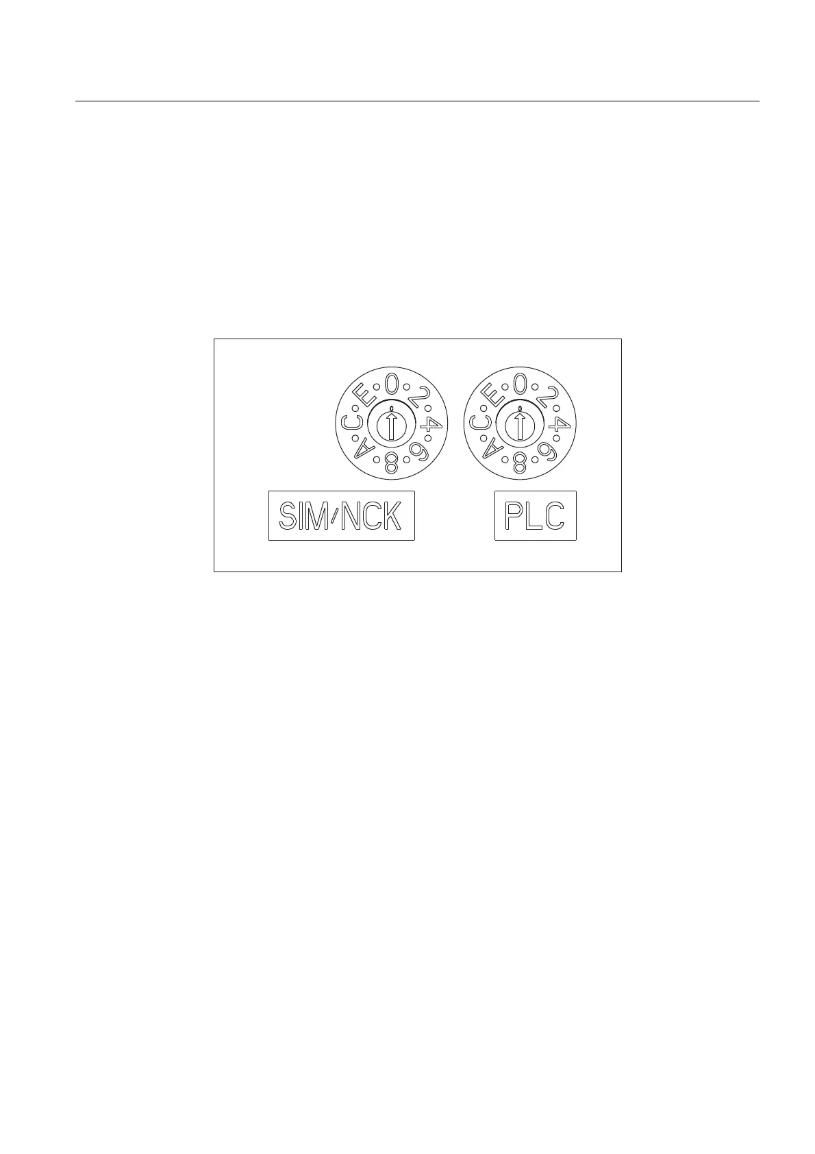
The Control Unit has two coding switches in the lower section of the front panel.
● The left switch (labeled SIM/NCK) is the NCK startup switch.
Setting during normal operation: "0"
● The right switch (labeled PLC) is the PLC mode selector switch.
Setting during normal operation: "0"
Figure 3-5 Startup and mode selector switch
Additional references
CNC Commissioning Manual Part 1 (NCK, PLC, drive)

 Loading...


