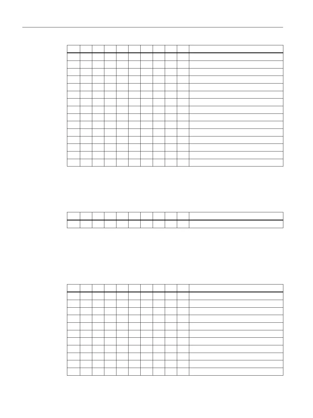
1 2 3 4 5 6 7 8 9 10 Meaning
on o on on o o o o Default device name: mcp-pn13
o o on on o o o o Default device name: mcp-pn12
on on o on o o o o Default device name: mcp-pn11
o on o on o o o o Default device name: mcp-pn10
on o o on o o o o Default device name: mcp-pn9
o o o on o o o o Default device name: mcp-pn8
on on on o o o o o Default device name: mcp-pn7
o on on o o o o o Default device name: mcp-pn6
on o on o o o o o Default device name: mcp-pn5
o o on o o o o o Default device name: mcp-pn4
on on o o o o o o Default device name: mcp-pn3
o on o o o o o o Default device name: mcp-pn2
on o o o o o o o Default device name: mcp-pn1
o o o o o o o o Default device name: mcp-pn
MCP set up as IE
You can assign a logical address to the MCP for communication via Ethernet with the 10-bit
switch S1.
Table 3-3 Setting of switch S1 as delivered
1 2 3 4 5 6 7 8 9 10 Meaning
o o o o o o on on o o MCP address 192
The two switches S1-9 and S1-10 must be set to "o" (IE functionality).
The switches S1-1 to S1-8 dene the MCP address in the range of 0 to 255.
The addresses from 192 to 223 count as the default range.
The MCP address is used as a reference for addressing an MCP during the PLC parameter
assignment.
Table 3-4 Settings of switch S1
1 2 3 4 5 6 7 8 9 10 Meaning
o o
on on on on on on on on MCP address 255
x x x x x x x x "
on on on on on o on on MCP address 223
o on on on on o on on MCP address 222
on o on on on o on on MCP address 221
o o on on on o on on MCP address 220
on on o on on o on on MCP address 219
o on o on on o on on MCP address 218
on o o on on o on on MCP address 217
Operator control and display elements
3.3 Interfaces
ONE MCP Part 1: MCP xxxx
22 Equipment Manual, 07/2020, A5E50324729B AA
 Loading...