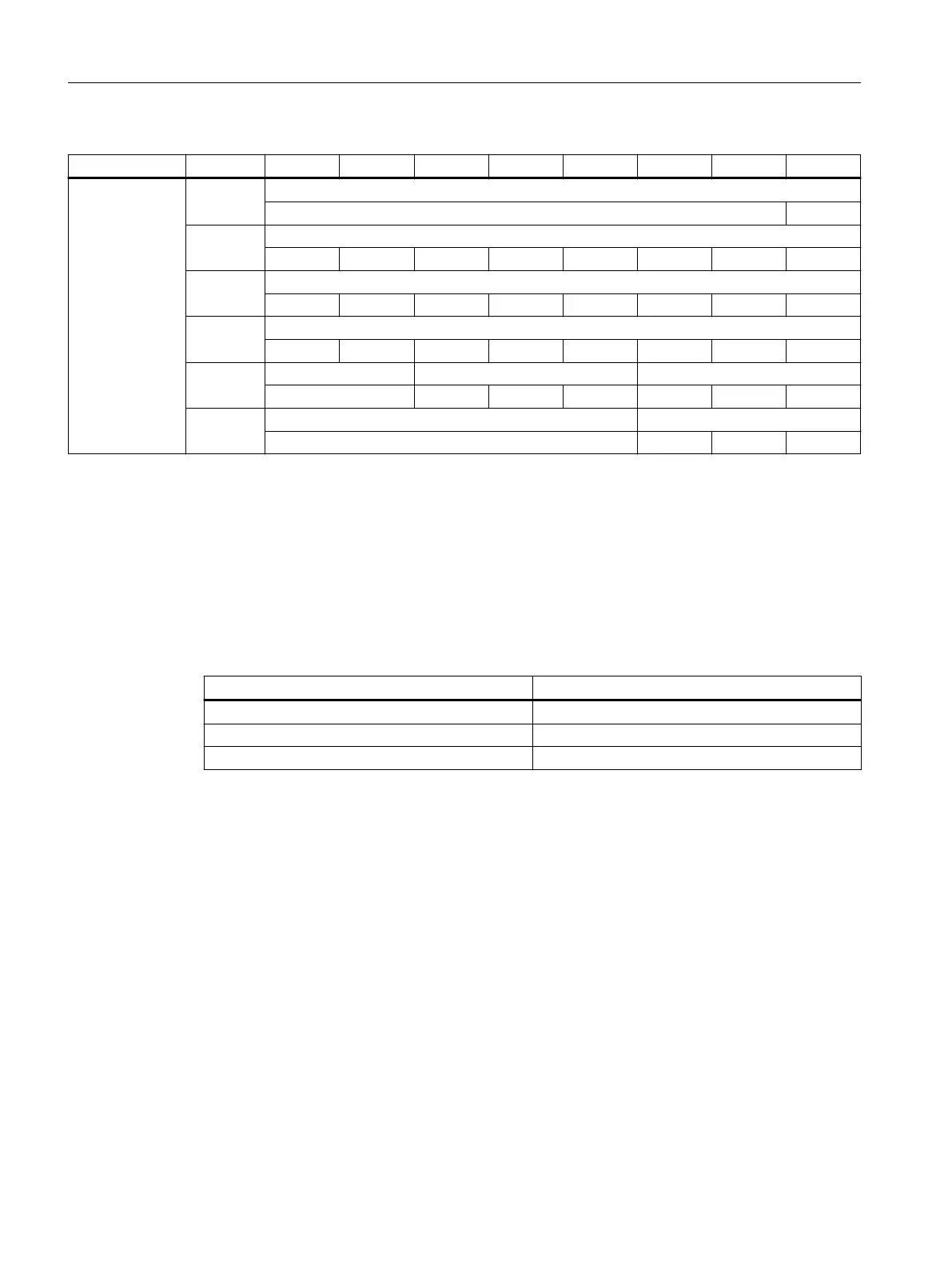
Slot Byte *) Bit7 Bit6 Bit5 Bit4 Bit3 Bit2 Bit1 Bit0
Powerride 3 AB n + 0 Powerride 3 LED scale
LED 24
AB n + 1 Powerride 3 LED scale
LED23 LED22 LED21 LED20 LED19 LED18 LED17 LED16
AB n + 2 Powerride 3 LED scale
LED15 LED14 LED13 LED12 LED11 LED10 LED9 LED8
AB n + 3 Powerride 3 LED scale
LED7 LED6 LED5 LED4 LED3 LED2 LED1 LED0
AB n + 4 Powerride 3 start button Powerride 3 color scale
Green Blue Green Red
AB n + 5 Vibration pattern
2
2
2
1
2
0
*): The logical address is made up of the oset and the start address from the hardware
conguration.
5.4 Changing the the color values of the key module LEDs
You can assign colors to the keys of a modular MCP to reect the status. Possible states are
"active" and "inactive".
You can nd details of the frame call in the "SINUMERIK ONE PLC" Function Manual.
Color Intensity
Red [0…255
d
]
Green [0…255
d
]
Blue [0…255
d
]
Connecting
5.4 Changing the the color values of the key module LEDs
ONE MCP Part 1: MCP xxxx
50 Equipment Manual, 07/2020, A5E50324729B AA
 Loading...