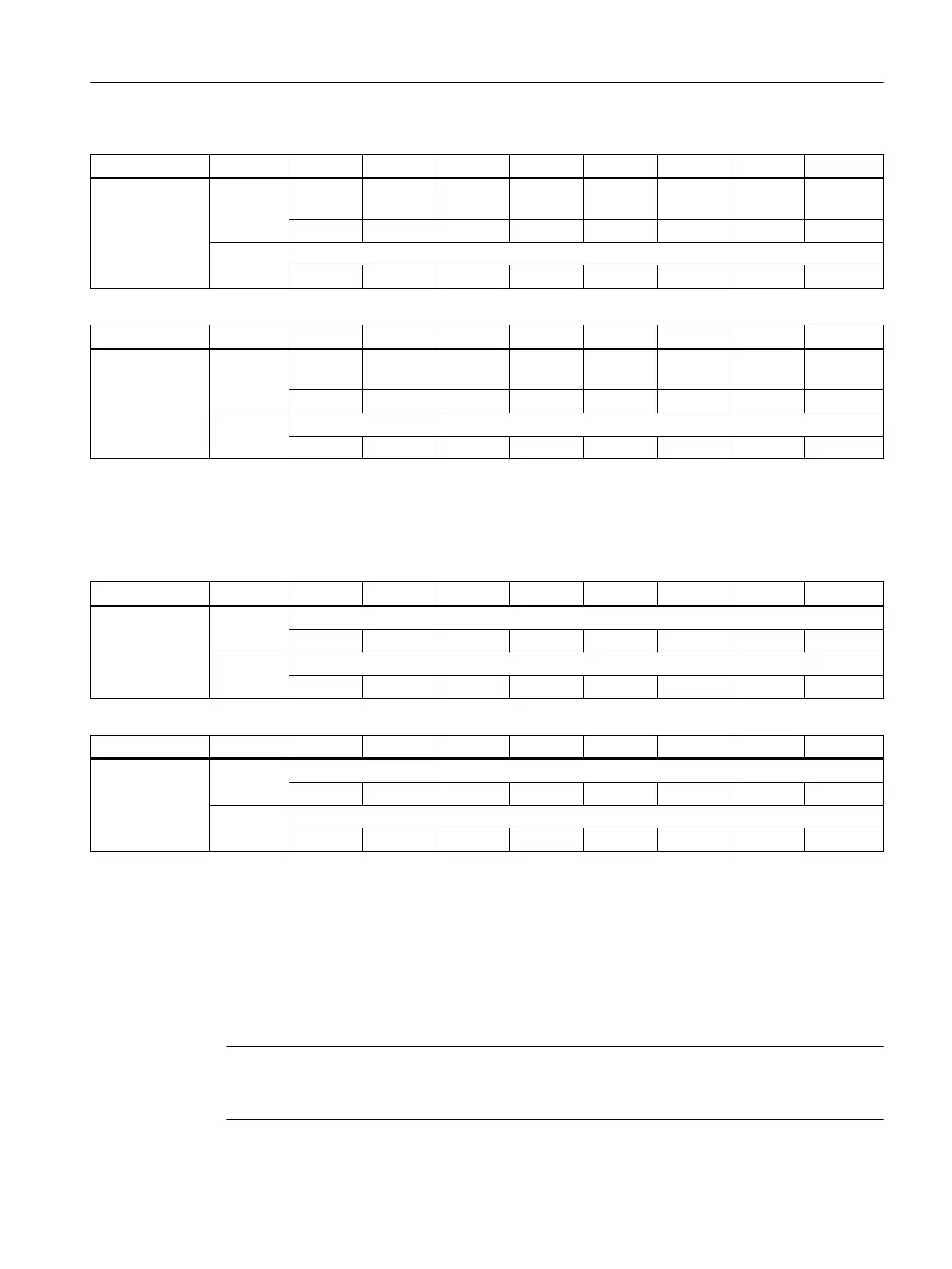
Slot Byte *) Bit7 Bit6 Bit5 Bit4 Bit3 Bit2 Bit1 Bit0
Powerride 2 EB n + 0 Start but‐
ton
- - - - - - Key1
EB n + 1 Counter Powerride 2
2
7
2
6
2
5
2
4
2
3
2
2
2
1
2
0
Slot Byte *) Bit7 Bit6 Bit5 Bit4 Bit3 Bit2 Bit1 Bit0
Powerride 3 EB n + 0 Start but‐
ton
- - - - - - Key1
EB n + 1 Counter Powerride 3
2
7
2
6
2
5
2
4
2
3
2
2
2
1
2
0
*): The logical address is made up of the oset and the start address from the hardware
conguration.
Handwheels
Slot Byte *) Bit7 Bit6 Bit5 Bit4 Bit3 Bit2 Bit1 Bit0
Handwheel 1 EB n + 0 Counter handwheel 1
2
7
2
6
2
5
2
4
2
3
2
2
2
1
2
0
EB n + 1 Counter handwheel 1
2
15
2
14
2
13
2
12
2
11
2
10
2
9
2
8
Slot Byte *) Bit7 Bit6 Bit5 Bit4 Bit3 Bit2 Bit1 Bit0
Handwheel 2 EB n + 0 Counter handwheel 2
2
7
2
6
2
5
2
4
2
3
2
2
2
1
2
0
EB n + 1 Counter handwheel 2
2
15
2
14
2
13
2
12
2
11
2
10
2
9
2
8
*): The logical address is made up of the oset and the start address from the hardware
conguration.
5.3 Output images
The specications for assigning input and output bytes listed in the tables can be changed in the
PLC via parameter assignment.
Note
The following applies in respect of the process input and output images in the tables: n is
dened by means of FB1 parameters in OB100 of the PLC.
Connecting
5.3 Output images
ONE MCP Part 1: MCP xxxx
Equipment Manual, 07/2020, A5E50324729B AA 47
 Loading...