7
Installation
SAR 28 A1
GB
IE
Accessories (see rear fold out fl ap)
Figure D:
29
Case for face plate
30
Installation bracket
31
Key for installation bracket
32
Anchoring plate (including securing material)
Installation
WARNING
Damage can be caused when installing the device!
► If possible, have the device installed by a qualifi ed technician.
► If you wish to install the device yourself, follow the instructions for connec-
tion and installation for safe, fault-free use of the device.
Connection
CAUTION
Using incorrect connections can cause damage to the device.
► For installation, use the device's ISO connections. The vehicle-specifi c ISO
adapters you may require can be sourced from a specialist workshop, from
a local dealer or from a general store's technical department. Using other
connector types voids the warranty.
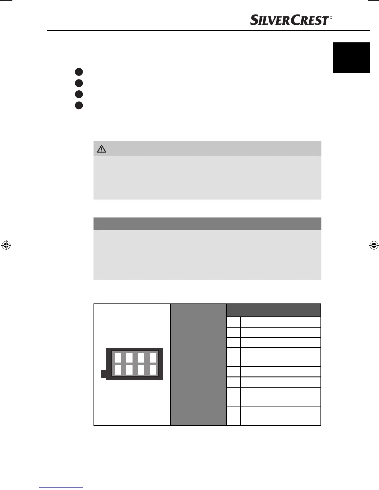
Assignment of the ISO connections
The view of the plug connector is from behind.
1357
2468
ISO A
(power supply
assignment)
Assignment
1 Not used
2 Not used
3 Not used
4
Steady plus 12 V
(terminal 30)
5 Antenna power
6 Not used
7
Ignition circuit positive 12 V
(terminal 15)
8
Negative (-)
ground (terminal 31)
IB_85465_SAR28A1_LB3.indb 7IB_85465_SAR28A1_LB3.indb 7 06.12.12 16:4706.12.12 16:47
 Loading...