9
Initial Assembly
INITIAL ASSEMBLY
NOTE: Once installed, the front and rear hitch mounting
brackets need not be removed.
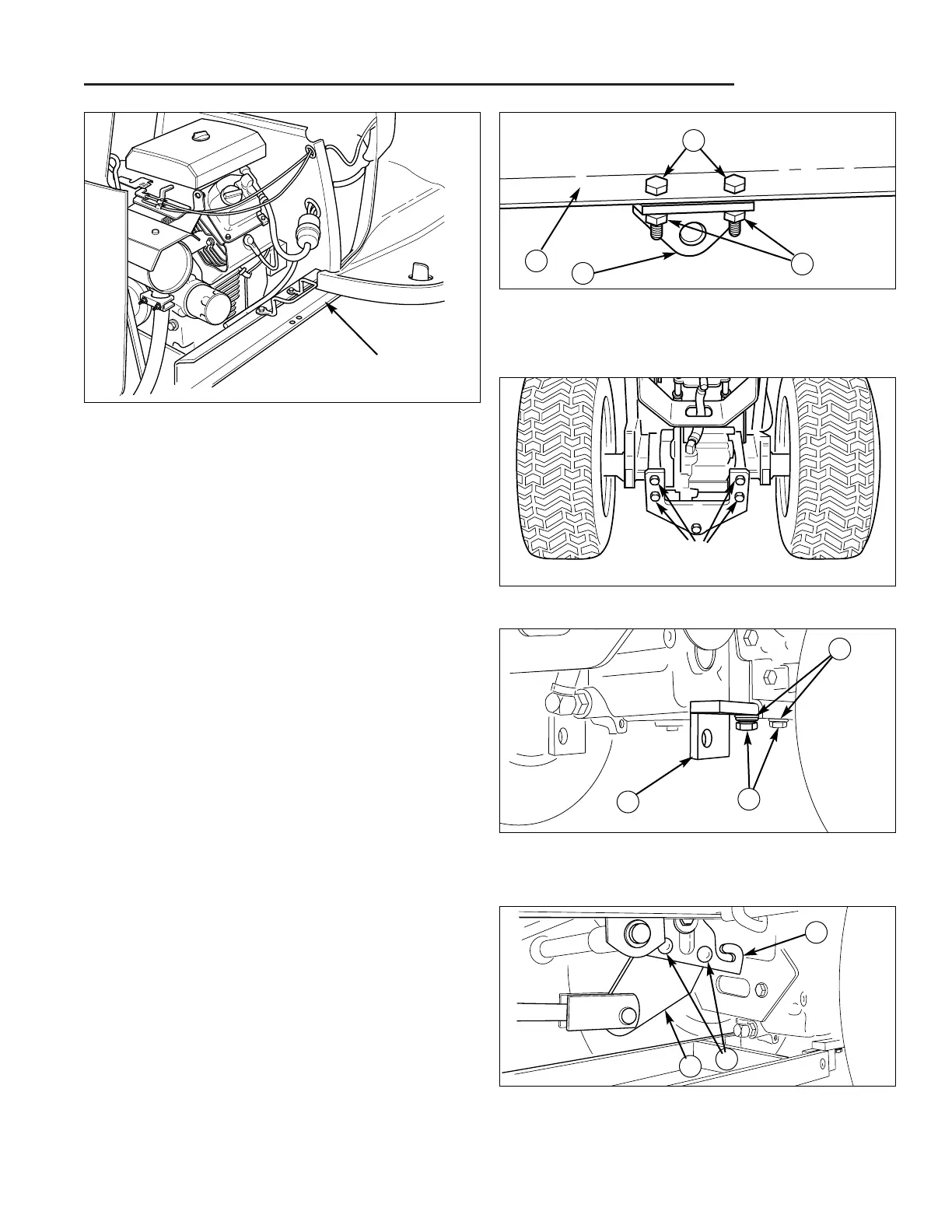
Install Front Hitch Mounting Brackets
Attach the front hitch mounting brackets (A Figure 13) to
the pre-drilled holes in both sides of the frame (see
Figure 12) using 5/16-18 x 1-1/4 capscrews, lockwash-
ers, and nuts.
Install Rear Hitch Mounting Brackets
1. Remove the front four capscrews and lockwashers
securing the drawbar to the transmission (see
Figure 13).
2. Attach the rear hitch brackets (A, Figure 15) to the
drawbar and transmission with the 5/8-11 x 2” cap-
screws (C) and washers (B) provided.
NOTE: During initial installation do not tighten the cap-
screws (C, Figure 15) securing the rear hitch mounting
brackets until the attachment is completely installed.
Install Attachment Lift Extension
NOTE: The attachment lift extension must
be removed when using a mower.
1. Install the attachment lift extension (B, Figure 16) on
the left attachment lift arm (A) using two 3/8-16 x 1”
carriage bolts (C), lockwashers, and nuts as shown in
Figure 16.
Drill Remote Deflector Control
Mounting Holes
1. Using the template included in the back of this manu-
al, drill two 9/32” holes in the dashboard to mount the
remote chute control. See DRILL HOLES TO
MOUNT REMOTE DEFLECTOR CONTROL.
Figure 14. Drawbar Bolts & Lockwashers
Bolts &
Lockwashers
Figure 13. Front Hitch Mounting Brackets
A. Hitch Bracket C. Capscrews,
B. Frame 5/16-18 x 1-1/4”
D. Nut & Lockwasher
A
D
B
C
Figure 15. Rear Hitch Brackets
A. Bracket C. Capscrew, 5/8-11 x 2”
B. Washer, 5/8
A
B
C
Figure 12. Front Hitch Bracket Mounting Holes
Bracket Mounting
Holes Located Here
Figure 16. Attachment Lift Extension
A. Lift Arm C. Carriage Bolt,
B. Lift Extension 3/8-16 x 1”
A
B
C
 Loading...