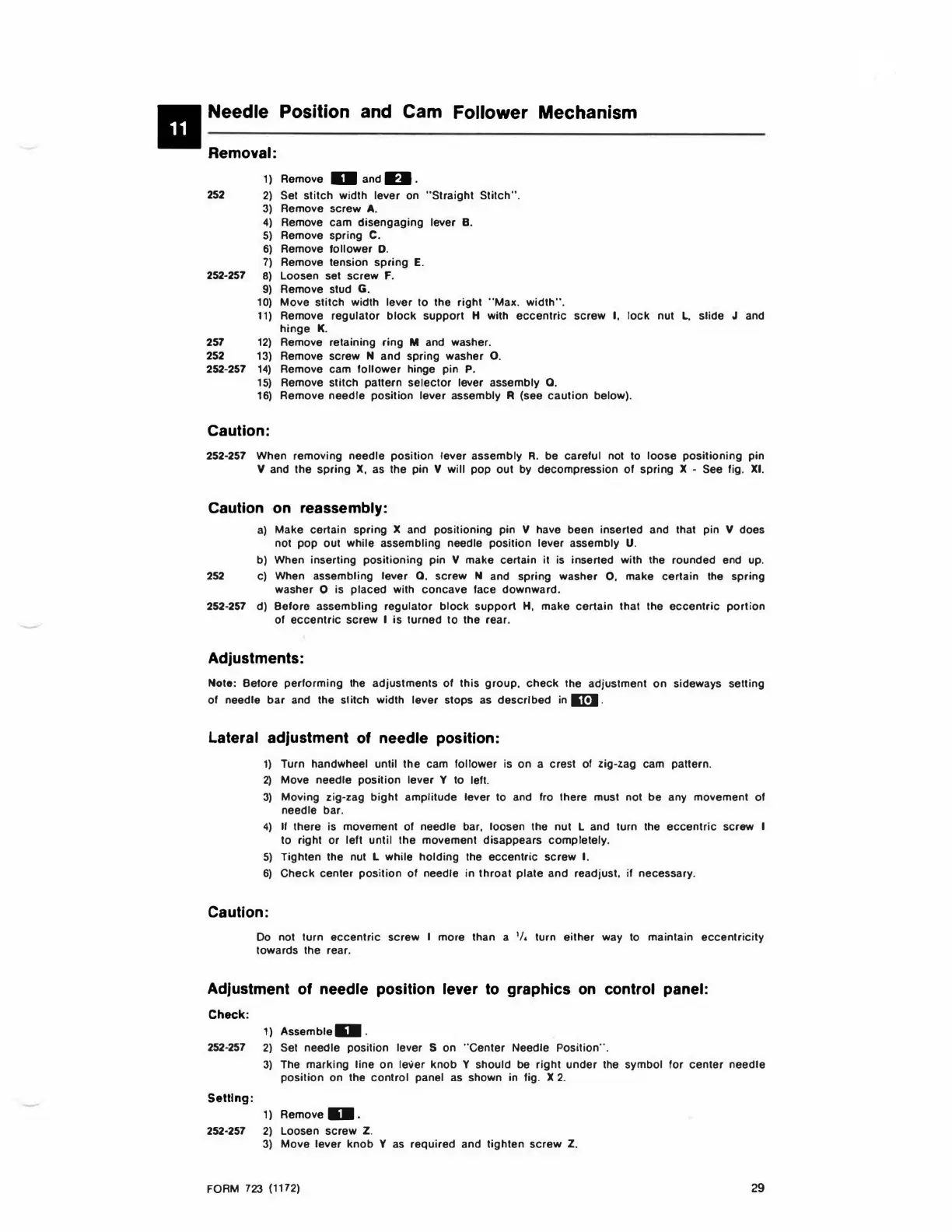
II Needle Position and Cam
Removal:
1)
Remove D and
0.
Follower Mechanism
252
2)
Set
stitch
width lever on
"Straight
Stitch"
.
3)
Remove
screw
A.
4)
Remove
cam
disengaging
lever
B.
5)
Remove spring
C.
6)
Remove
follower
D.
7)
Remove tension
spring
E.
252-257
8)
Loosen set
screw
f .
9)
Remove stud
G.
10)
Move
stitch
width lever
to
the
right
"Max.
width"
.
11)
Remove
regulator
block
support
H with
eccentric
screw
I,
lock
nut
L.
slide J and
hinge
K.
257
12)
Remove retaining
ring
M and washer.
252
13)
Remove screw N
and
spring washer
0.
252-257
14)
Remove cam
follower
hinge pin P.
15)
Remove
stitch
pattern
selector
lever assembly
0.
16)
Remove
needle
position
lever
assembly R (see
caution
below).
Caution:
252-257 When removing
needle
position
lever
assembly
R. be
careful
not to
loose
positioning
pin
V and the
spring
X,
as the pin V will
pop
out
by decompression
of
spring X - See fig.
XI
.
Caution
on
reassembly:
a)
Make certain spring X and
positioning
pin V have been inserted and that pin V does
not
pop
out
while assembling needle
position
lever
assembly U.
b) When inserting
positioning
pin V make certain it is inserted with the rounded end up.
252 c) When assembling
lever
0.
screw
N and spring washer
0,
make
certain
the
spring
washer O is
placed
with
concave
lace
downward
.
252-257 d)
Before
assembling
regulator
block
support
H, make
certain
that the
eccentric
portion
of
eccentric
screw
I
is
turned
to
the rear.
Adjustments:
Note: Before
performing
the
adjustments
of
this
group
.
check
the adjustment
on
sideways setting
of
needle
bar
and the stitch width lever stops as
described
in
IE.I.
Lateral adjustment
of
needle position:
1)
Turn handwheel until
the
cam
follower
is
on
a crest of zig-zag cam pattern.
2)
Move needle
position
lever
Y to left.
3)
Moving
zig-zag
bight
amplitude
lever
to and fro there must not
be
any movement
ol
needle bar.
4)
II there is movement
of
needle bar, loosen the nut L and turn the
eccentric
screw I
to right
or
left
until
the movement
disappears
completely.
5)
Tighten the nut l while
holding
the
eccentric
screw
I.
6)
Check
center
position
of
needle
in
throat
plate
and
readjust.
if
necessary.
Caution:
Do not turn
eccentric
screw
I more than a
'/,
turn
either
way to maintain
eccentricity
towards the rear.
Adjustment
of
needle position lever
to
graphics
on
control panel:
Check:
1) Assemb
te
D .
252-257
2)
Set needle position lever S on " Center Needle Position
".
3)
The marking
line
on
lever
knob
Y
should
be
right
under
the symbol for
center
needle
position
on the
control
panel as shown in fig. X 2.
Setting:
1) Ae
mo
ve
D .
252-257
2)
Loosen
screw
Z.
3)
Move
lever
knob
Y as
required
and
tighten
screw
Z.
FOAM
723
(1172)
29
 Loading...