DSAT-300 USER GUIDE 26
Document Rev. 1.015 DOC0594 Page 26 of 28
Restricted Proprietary and Confidential Information
15.1 POWER CONNECTOR
View of DSAT-300 power interface
15.1.1 PINS
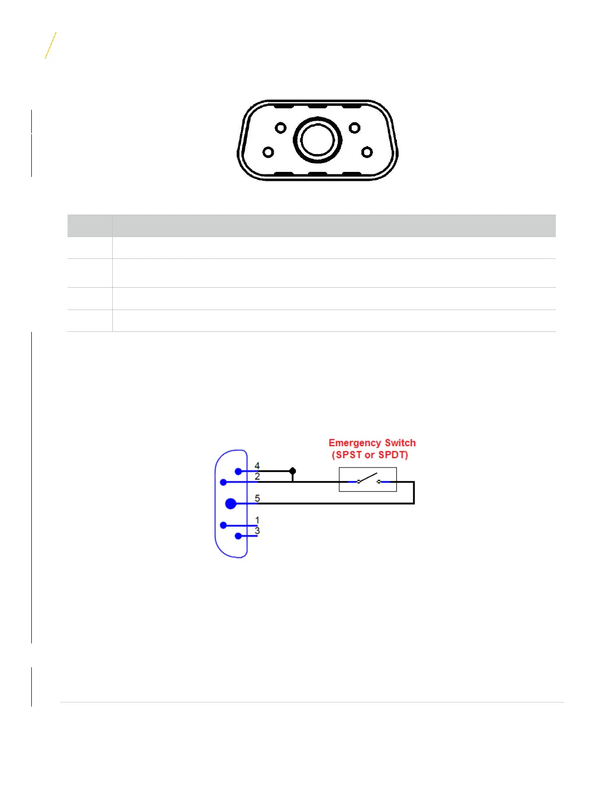
15.1.1 External Emergency Switch
Emergency Mode can be controlled through an external switch by simultaneously shorting pins 2 and 4 to ground
(Pin 5/A1). This can be accomplished by using a SPST or SPDT switch, similar to the wiring diagram below.
Firmware for the Emergency Switch feature must be 04.02 or greater. Users can “QUERY” the unit in the
Hardware Management section of SkyWeb to determine the current firmware version.
Figure 15 1 Example External Emergency Switch Wiring
NOTE: When wired as shown above, other functions controlled by pins 2 or 4 cannot be initiated. To use these
functions, a separate wiring harness may be required.

 Loading...