SkyTrac Systems Ltd.
Document Rev. 02.010 ISAT-100-OPD-SOI Page 9 of 26
Restricted Proprietary and Confidential Information
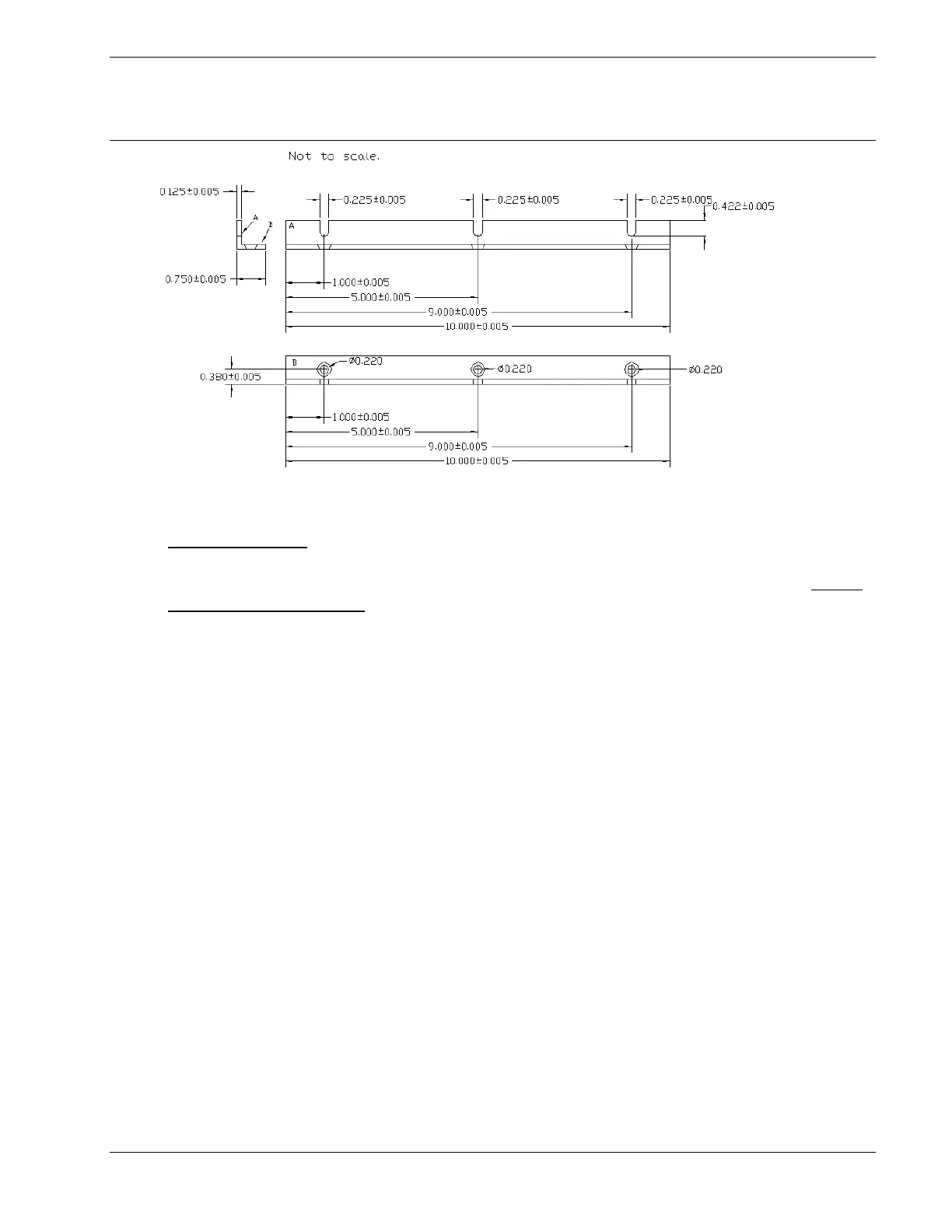
FIGURE 4-1 ISAT-100 Mounting Rails
Important Note:
The ISAT-100 contains a sealed lead-acid battery as a backup power source. Under
extreme fault conditions, this device may release Hydrogen gas at a rate of up to
0.84 in
3
per minute. The installer must install this device in an area with sufficient
ventilation and comply with FAR 29.1353 (c) for the final installation design.
The ISAT-100 must be mounted in an upright position or a sideways position
and none of the venting holes in the top cover or in either side panel should be
covered at any time. The ISAT-100 may not be mounted inverted. (See
Installation Limitations.)
The free air volume around the ISAT-100 installation must be at least 8 cubic feet.
Like any other transmitter, the ISAT-100 should be installed as far from aircraft
apertures (such as windows) and as far from radio receiver antennae as practical.
Figure 4.2 illustrates the Block Diagram for the ISAT-100.
Refer to ISAT-100 Optional Equipment Wiring Diagram (DOC0029) if the applicable
STC drawings are not available.
The document reference is online, please check the correspondence between the online documentation and the printed version.
 Loading...