SkyTrac Systems Ltd.
Document Rev. 02.010 ISAT-100-OPD-SOI Page 10 of 26
Restricted Proprietary and Confidential Information
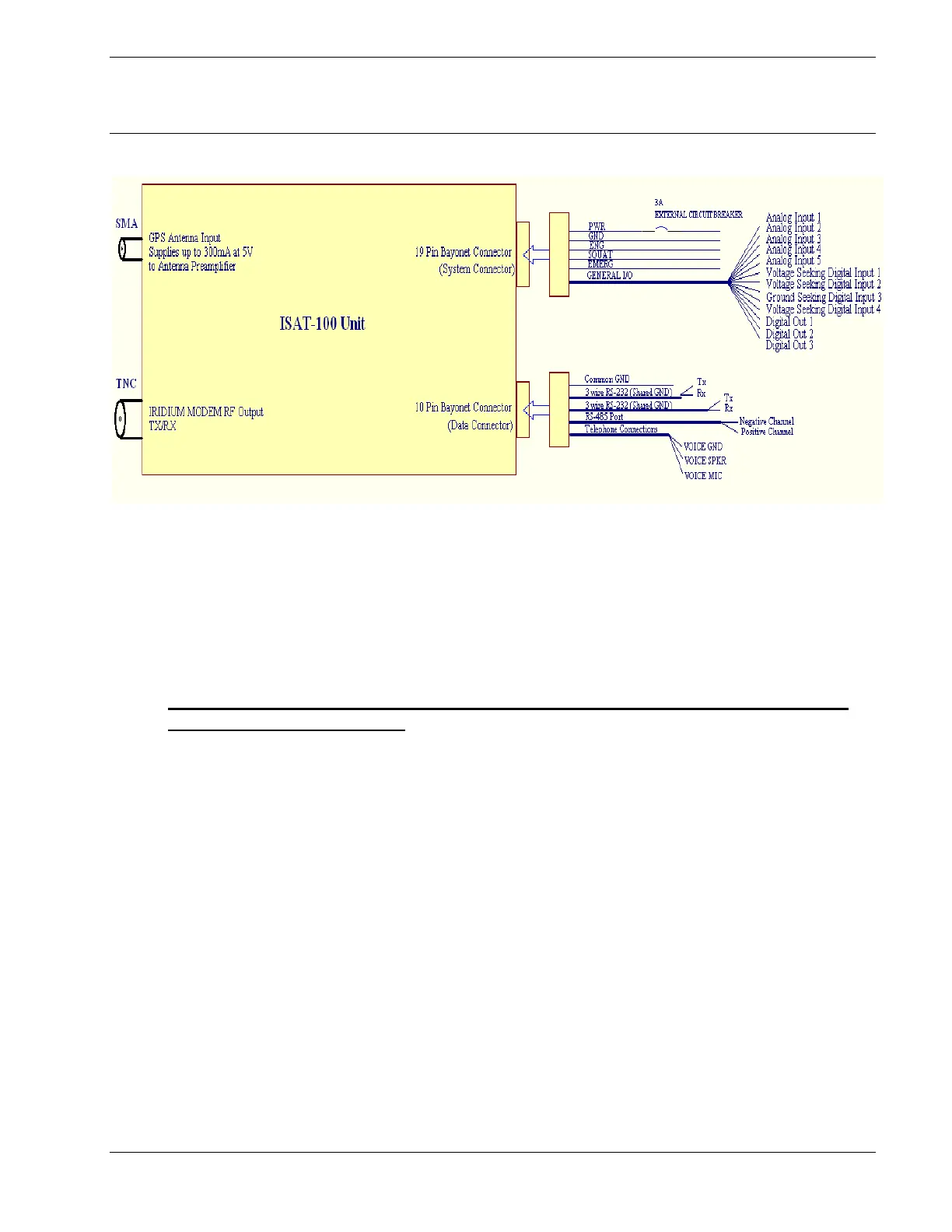
FIGURE 4-2 ISAT-100 Block Diagram
4.4.1 Pin Locations and Connections
The identification letters and descriptions for the 19-pin System Connector and 10-pin
Data Connector, located on the front of the ISAT-100, are listed in Tables 4-1 and 4.2
and illustrated in Figures 4-3 and 4.4 respectively.
Both Pin B and Pin C on the System connector must be grounded in order to
enable the internal battery.
Use AWG 20 wire to hook up the 28VDC aircraft main power source protected
through a 3 Amp breaker to the ISAT-100. It is important to remember that the ISAT-
100 will sense the onrush of 28VDC and will send this event, together with a
timestamp, to the dispatch centre in order to signal the beginning of a flight. Thus, the
ISAT-100 should receive mains power as soon as the aircraft’s master or avionics
switch is turned on. The remaining Pins on J1 are reserved for future firmware
implementations.
The document reference is online, please check the correspondence between the online documentation and the printed version.
 Loading...