HRX-OM-W058
Chapter 7 Alarm indication and trouble shooting
HRS-R Series 7.1 Alarm Display
Chapter 7 Alarm indication and trouble
shooting
7.1 Alarm Display
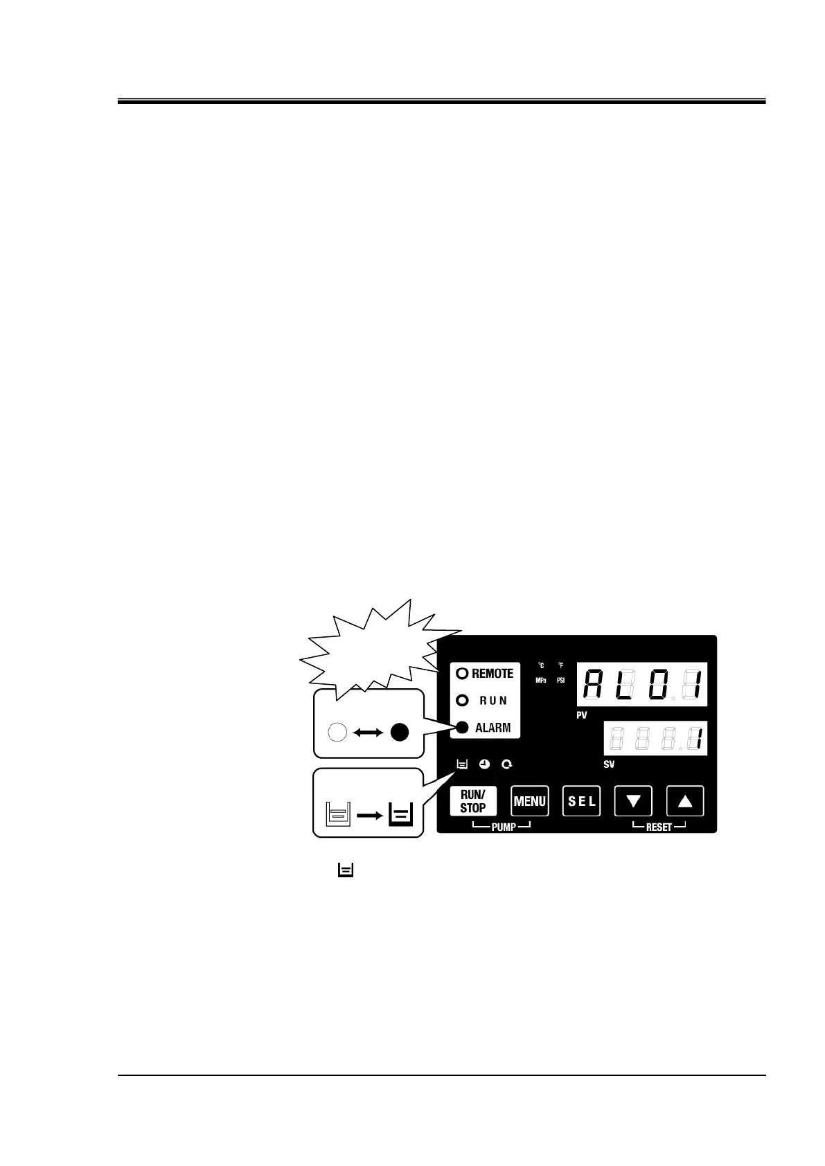
When any alarm occurs, the product responds with the following conditions.
The [ALARM] lamp will flash.
The alarm buzzer sounds.
The alarm no. is displayed on PV.
Contact signal of contact input/output communication is output.
Refer to the Operation Manual for communication for details.
Read alarm status with serial communication.
Refer to the Operation Manual for communication for details.
The thermo-chiller has two types of operation depending on the alarm
status.
One alarm type will stop operation when an alarm is generated during
operation. The other type will not stop operation even when an alarm is
generated.
Refer to the “Table 7-1 Alarm code list and Troubleshooting”. When the
operation is forced to stop, the product cannot restart until the alarm is
reset.
[ ] lamp lights only when AL01 Low tank level is generated.
 Loading...


