EasyManuals Logo
Home>SMC Networks>Chiller>HRS018-A 20 R Series

SMC Networks HRS018-A 20 R Series User Manual

Default Icon
162 pages
To Next Page IconTo Next Page
To Previous Page IconTo Previous Page
Page #149 background imageLoading...
Page #149 background image
HRX-OM-W058
Chapter 9 Documents
HRS-R Series 9.1 Specifications List
9-3
9.1.3 Communication specifications
Contact input/output
Table 9-3 Specifications List
Item
Specification
Connector type (for this product)
MC1,5/12-GF-3,5
For option B:
DFK-MC1,5/12-GF-3,81
Input signal
Insulation system
Photo coupler
Rated input Voltage
DC24V
Operating voltage range
DC21.6V to 26.4V
Rated input current
5mA TYP
Input signal
4.7kΩ
Contact output signal
Rated load voltage
AC48V or less /DC30V or less
Maximum load current
AC/DC500mA (Resistance load)
Minimum load current
DC5V 10mA
Output voltage
DC24V±10% 0.5A MAX
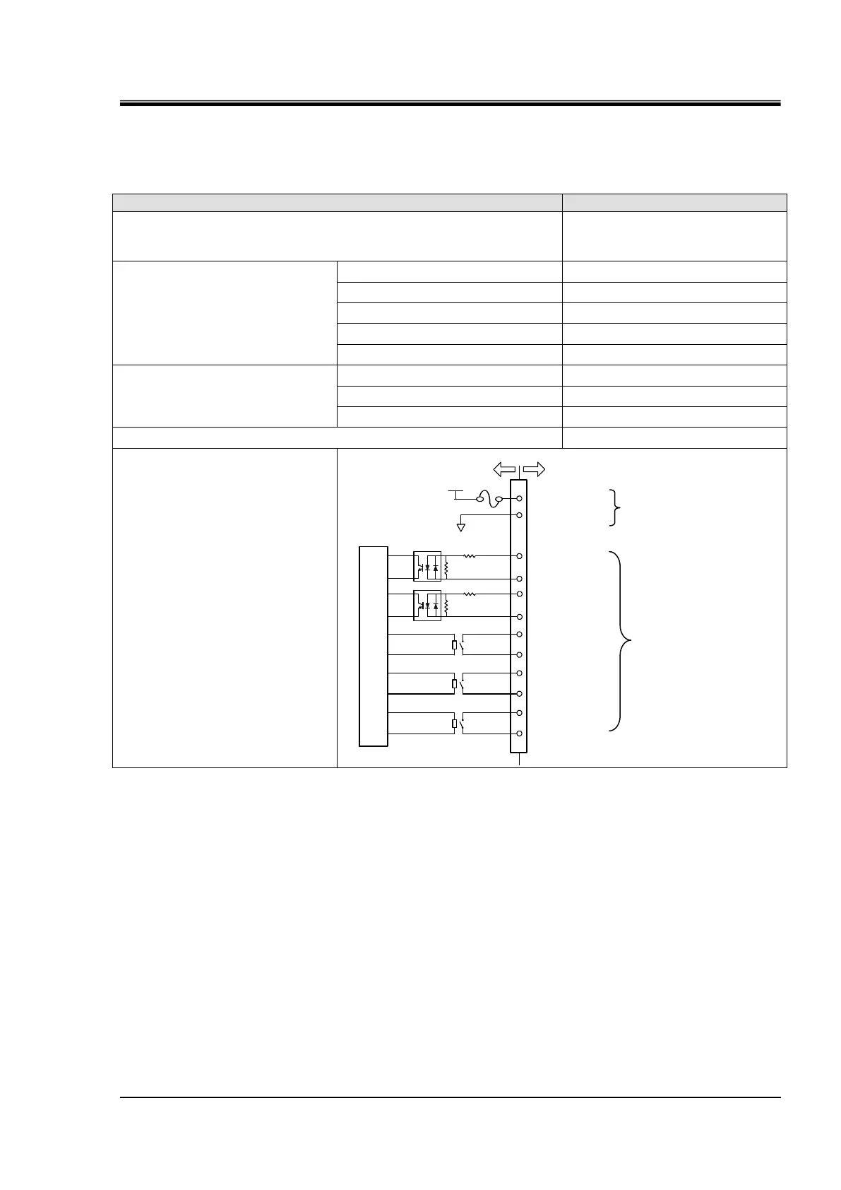
Circuit structure diagram
*1 The pin numbers and output signals can be set by user. For details, refer to the [5.19 Communication function].
*2 When using with optional accessories, depending on the accessory, the allowable current of 24 VDC devices will be reduced.
Refer to the operation manual of the optional accessories for details.
0.5A MAX
*2
Settings at the time of
shipment from the factory
*1
(Users can modify the
settings.)
4.7kΩ
This product
Your system
Internal circuit
DC24V
Alarm signal
10
6
Run/stop signal
Run status signal
Remote signal
12
11
24VCOM
9
8
7
5
4
3
2
1
Default unsetting
DC24V output
24VCOM output
1kΩ
4.7kΩ
1kΩ

Table of Contents

Questions and Answers:

Question and Answer IconNeed help?

Do you have a question about the SMC Networks HRS018-A 20 R Series and is the answer not in the manual?

SMC Networks HRS018-A 20 R Series Specifications

General IconGeneral
BrandSMC Networks
ModelHRS018-A 20 R Series
CategoryChiller
LanguageEnglish

Related product manuals