HRX-OM-O021
Chapter 8 Documents
8.1 Specifications List HRS Series
8-2
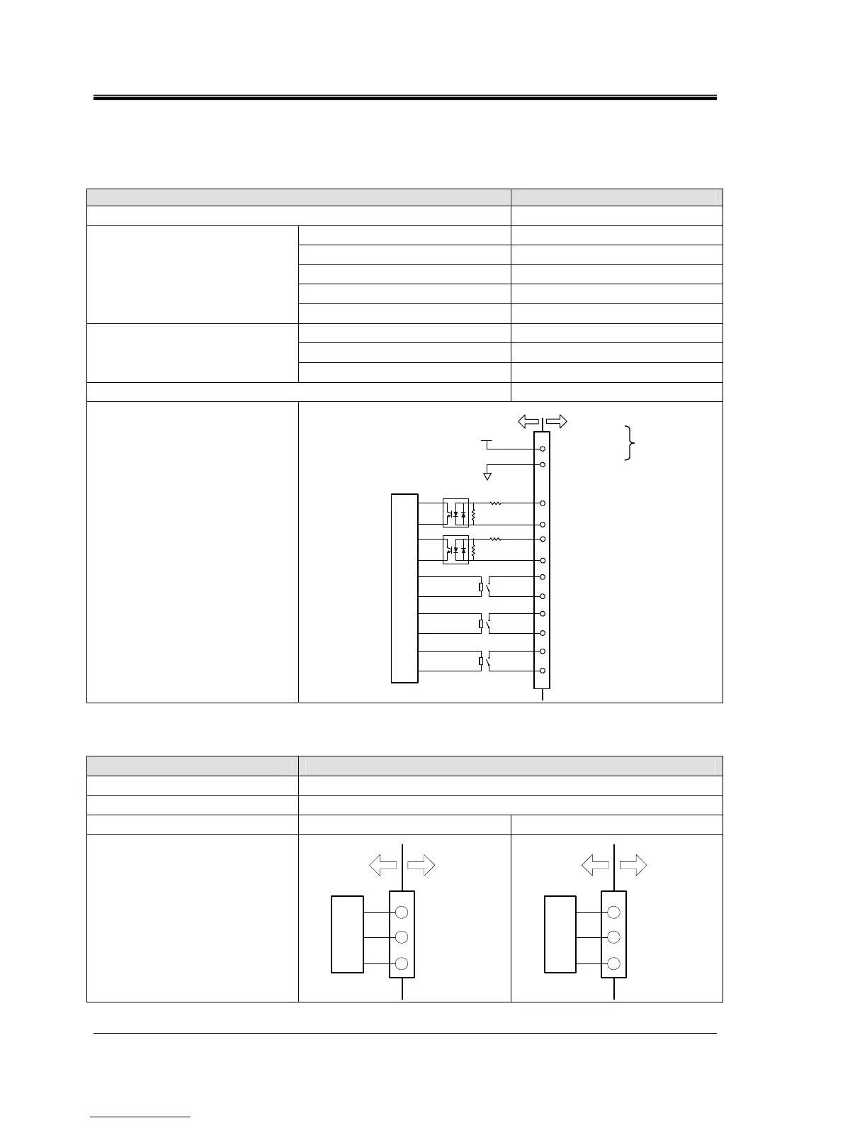
8.1.2 Communication specifications
Contact input/output
Table 8-2 Specifications List
Item Specification
Connector type (for this product) MC1,5/12-GF-3,5
Insulation system Photo coupler
Rated input Voltage DC24V
Operating voltage range DC21.6V to 26.4V
Rated input current
5mA TYP
Input signal
Input signal 4.7Ω
Rated load current AC48V or less /DC30V or less
Maximum load current AC/DC500mA (Resistance load)
Contact output signal
Minimum load current DC5V 10mA
Output voltage DC24V±10% 0.5A MAX
Circuit structure diagram
4.7kΩ
This product
Your system
Internal circuit
DC24V
Alarm signal
10
6
Run/stop signal
Run status signal
Remote signal
12
11
24VCOM
9
8
7
5
4
3
2
1
Default unsetting
DC24V output
24VCOM output
1kΩ
4.7kΩ
1kΩ
Serial communication
Table 8-3 Specifications List
Item Specification
Connector type (for this product) D-sub9 pin Female connector
Protocol Modicon Modbus standard / Simple communicationprotocol
Standard
EIA RS-485 EIA RS-232C
Circuit structure diagram
1
5
9
internal circuit
This product Your system
SD+
SG
SD-
2
3
5
internal circuit
This product Your system
RD
SD
SG
0.5A MAX

 Loading...