HRX-OM-O021
Chapter 5 Display and setting of various functions
HRS Series 5.4 Inspection monitor menu
5-11
Check of the pressure of the lower pressure side of the refrigerant circuit
6. Press the [SEL] key once.
The pressure of lower pressure refrigerant circuit is displayed on the digital display.
PV
SV
Displays the pressure of the lower pressure side of the refrigerant circuit.
Check of the electric resistivity
7. Press the [SEL] key once.
The electric resistivity is displayed on the digital display.
PV
SV
This function is available for customers who have purchased the electric resistivity
sensor set (part no.: HRS-Dl001).
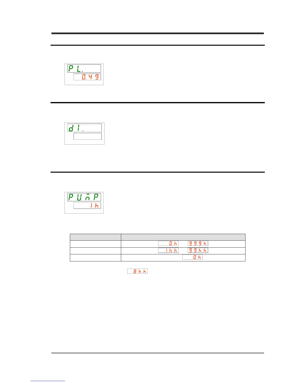
Check of the accumulated operation time of the pump
8. Press the [SEL] key once.
The accumulated operation time of the pump is displayed on the digital display.
PV
SV
Displays the accumulated operation time of the pump. Refer to the table below for the
display.
Table 5.4-2 List of time display
Cumulative time Indicated value
0h to 999h
to
1,000h to 99,999h
to
100,000h
Return to
AL28 Pump maintenance alarm is generated when the accumulated operation time of the
pump reaches 8,000 hours (
) or more. For details, refer to Chapter 6 Alarm
indication and trouble shooting
.

 Loading...