HRX-OM-O021
Chapter 5 Display and setting of various functions
HRS Series 5.15 Alarm customize function
5-37
Table 5.15-2 List of set alarm customize function(2/2)
Display Item Contents
Initial value
(Default setting)
Changing of electric
resistivity drop
Set the operation when the alarm No. AL35
“Electric resistivity drop” is generated.
OFF
Lower limit of electric
resistivity drop
Sets the detection level for the alarm of alarm
NO. AL35 "Electric resistivity drop".
Alarm signal is generated when the level
becomes lower than this level.
0.2MΩ・cm
Temperature alarm
Monitoring method
One alarm monitoring method can be selected
from four methods for AL04 "Detection temp for
the circulating fluid discharge temp. increase"
and AL06 "Detection temp. for circulating fluid
discharge temp. drop".
0
Monitoring start timer
Alarm will not be generated during the set period
of time after starting operation. Alarm monitoring
starts when it reaches the set time.
----
Range over
Detection timer
After starting the alarm monitoring, the alarm will
not be generated right away and will be kept not
generated for the set period of time for AL04
"Detection temp for the circulating fluid discharge
temp. increase" and AL06 "Detection temp. for
circulating fluid discharge temp. drop", when the
temperatures goes out of the set range.
5
*1:This function is available for customers who have purchased the drain pan set (part no.: HRS-WL002).
*2 : This function is available for customers who have purchased the electric resistivity sensor set (part no.:
HRS-Dl001).
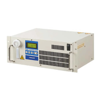
1. Press and hold the [MENU] key for approx. 2 sec.
Repeat pressing the key until the setting screen for alarm buzzer sound [
]
appears on the digital display.
PV
SV
PV
SV
PV
SV
PV
SV
Low tank level Setting and checking
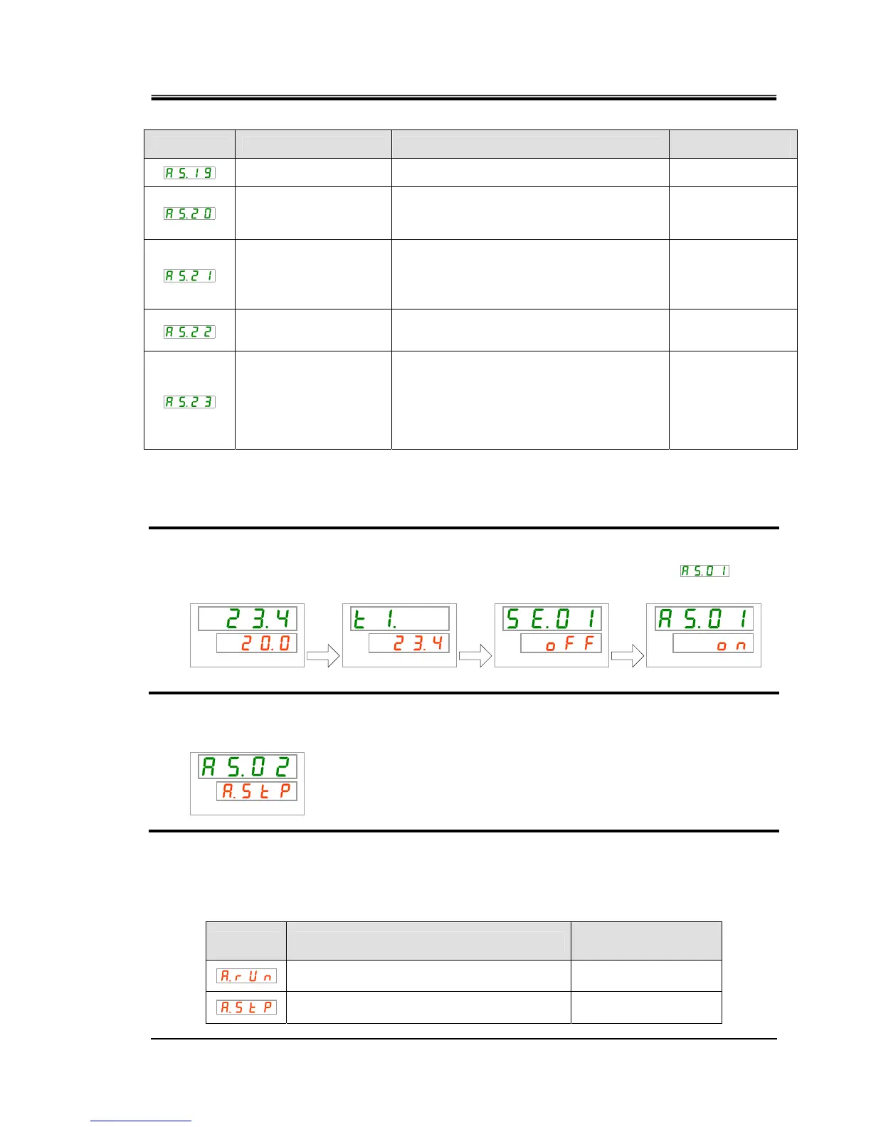
2. Press the [SEL] key once.
The set screen of changing of low tank level is displayed on the digital display.
PV
SV
3. Select changing of low tank level from the table below with [▲] key or [▼] key, and
confirm by pressing “SEL”.
Table 5.15-3 List of set value
Set value Explanation
Initial value
(Default setting)
Operation continues when this alarm signal is
generated.
Operation is stopped when this alarm signal is
generated.
○
[MENU]
Press and
hold
[MENU]
Press and
hold
[MENU]
Press and
hold

 Loading...