- 20 -
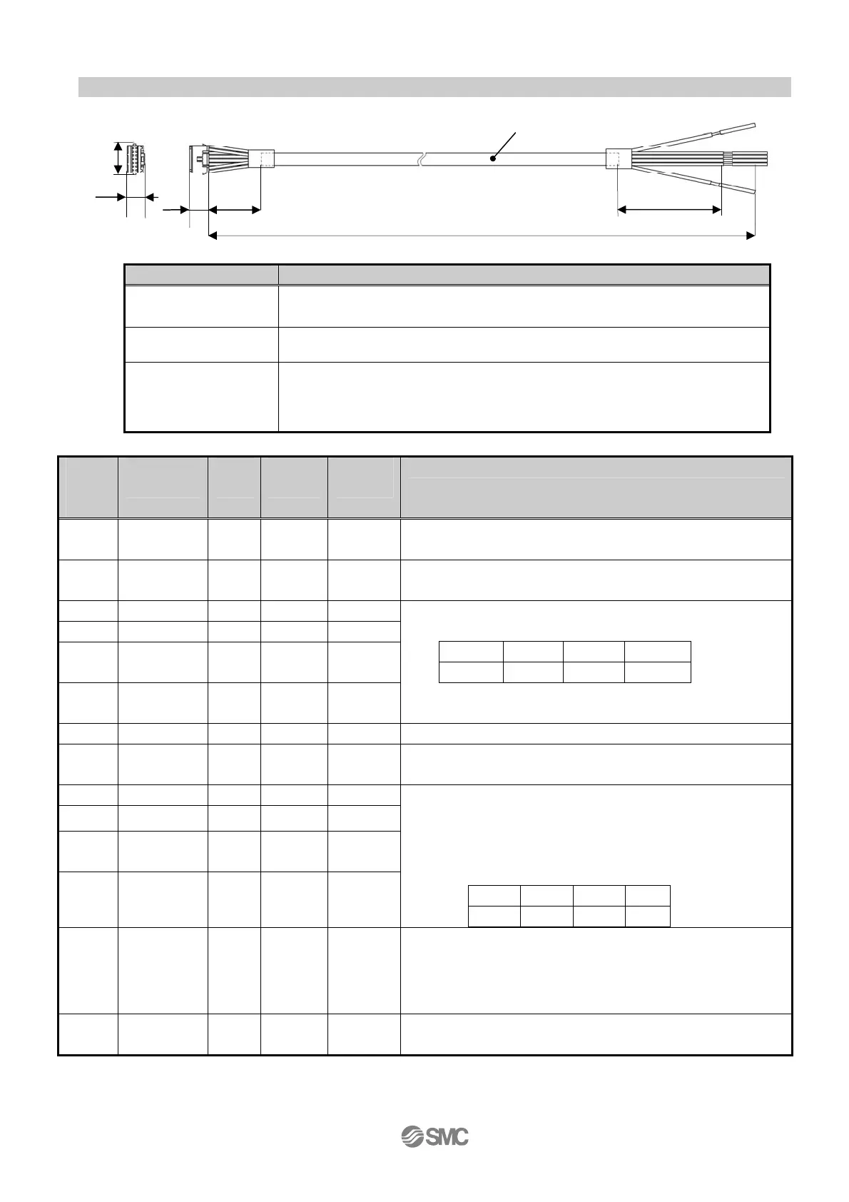
6.3 Parallel input / output signal
Item Specifications
Connector
Manufacturer: J.S.T. Mfg. Co.,Ltd.Manufacturer: J.S.T. Mfg. Co.,Ltd.
Product number :PADP-14V-1-S
Cross sectional
area of the cable
AWG26
Length (L)
The suffix of the part number (1,3,5) specifies the length.
LEC-CK4-1: 1.5m
LEC-CK4-3: 3m
LEC-CK4-5: 5m
Termi
nal
No.
Insulation
color
Dot
Mark
Dot
color
Func
tion
Contents
1 Light
brown
■ Black COM+ Connect the 24V side of the power supply (24VDC) for
input / output signal.
2 Light
brown
■ Red COM- Connect the 0V side of the power supply (24VDC) for
input / output signal.
3 Yellow ■ Black OUT0
4 Yellow ■ Red OUT1
5 Light
green
■ Black OUT2
6 Light
green
■ Red OUT3
Operation completion output (Output with the
combination of OUT0 to 3)
OUT3 OUT2 OUT1 OUT0
OFF OFF ON ON
7 Gray ■ Black BUSY BUSY signal (Output during operation)
8 Gray ■ Red ALARM ALARM signal N.C.
(Turned off during alarm or when servo is turned off)
9 White ■ Black IN0
10 White ■ Red IN1
11 Light
brown
■■ Black IN2
12 Light
brown
■■ Red IN3
・Operation command input
(Input with thecombination of IN0 to IN3)
・Input return to origin position command
(Turn on IN0 to 3 simultaneously)
Ex. (Commands position number 5 to operate)
IN3 IN2 IN1 IN0
OFF ON OFF ON
13 Yellow ■■ Black RESET
Interruption or alarm reset
During operation: The speed is reduced from the point
where signal is input until the
actuator stops. (Servo stays ON)
Alarm is being generated: Alarm reset
14 Yellow ■■ Red STOP STOP command (Sudden deceleration to turn off
servo)
* Parallel I/O signal is valid in auto mode. While the test function operates at manual mode, only the
output is valid.
PLC side
L
30
60
(
7.9)
10
11
(16)
I/O cable
LEC-CK4-□)
Controller side

 Loading...


