EasyManuals Logo
Home>SMC Networks>Controller>LECP1 Series

SMC Networks LECP1 Series User Manual

SMC Networks LECP1 Series
76 pages
To Next Page IconTo Next Page
To Previous Page IconTo Previous Page
Page #23 background imageLoading...
Page #23 background image
- 22 -
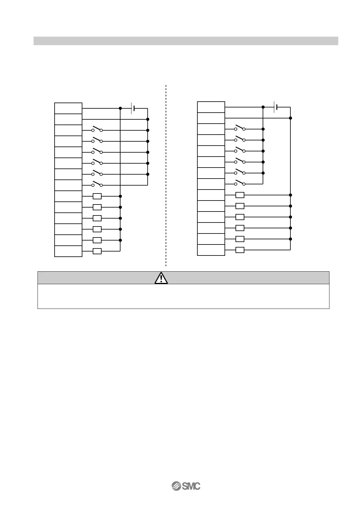
6.4 Parallel I/O connector wiring (Example)
Use an I/O cable (LEC-CK4-) when connecting to PLC and CN4 parallel I/O connectors.
Wiring depends on the parallel input/output of the controller (NPN, PNP type).
Please wire the product referring to the wiring diagram,
NPN TYPE PNP TYPE
Caution
Prepare separate 24VDC power supplies for the CN1 controller input power supply and CN4
input / output signal power supply.
COM +
COM -
IN0
IN1
IN2
IN3
RESET
STOP
OUT0
OUT1
OUT2
OUT3
BUSY
ALARM
Load
I/O signal power
supply DC24V
COM +
COM -
IN0
IN1
IN2
IN3
RESET
STOP
OUT0
OUT1
OUT2
OUT3
BUSY
ALARM
Load
I/O signal power
supply DC24V

Table of Contents

Other manuals for SMC Networks LECP1 Series

Questions and Answers:

Question and Answer IconNeed help?

Do you have a question about the SMC Networks LECP1 Series and is the answer not in the manual?

SMC Networks LECP1 Series Specifications

General IconGeneral
BrandSMC Networks
ModelLECP1 Series
CategoryController
LanguageEnglish

Related product manuals