- 59 -
12. Alarm detection
Details of the alarm can be checked by the controller LED indication and parallel I/O terminal.
When an alarm is generated, deactivate the alarm by troubleshooting, referring to 12.2 Alarm
Content・Countermeasure (P.
60).
Alarms are divided into two types. One type can be cleared by pressing the set button
○
g or inputting
the RESET I/O signal. The other type cannot be cleared unless the power supply control(C24V) is
turned off and on once.
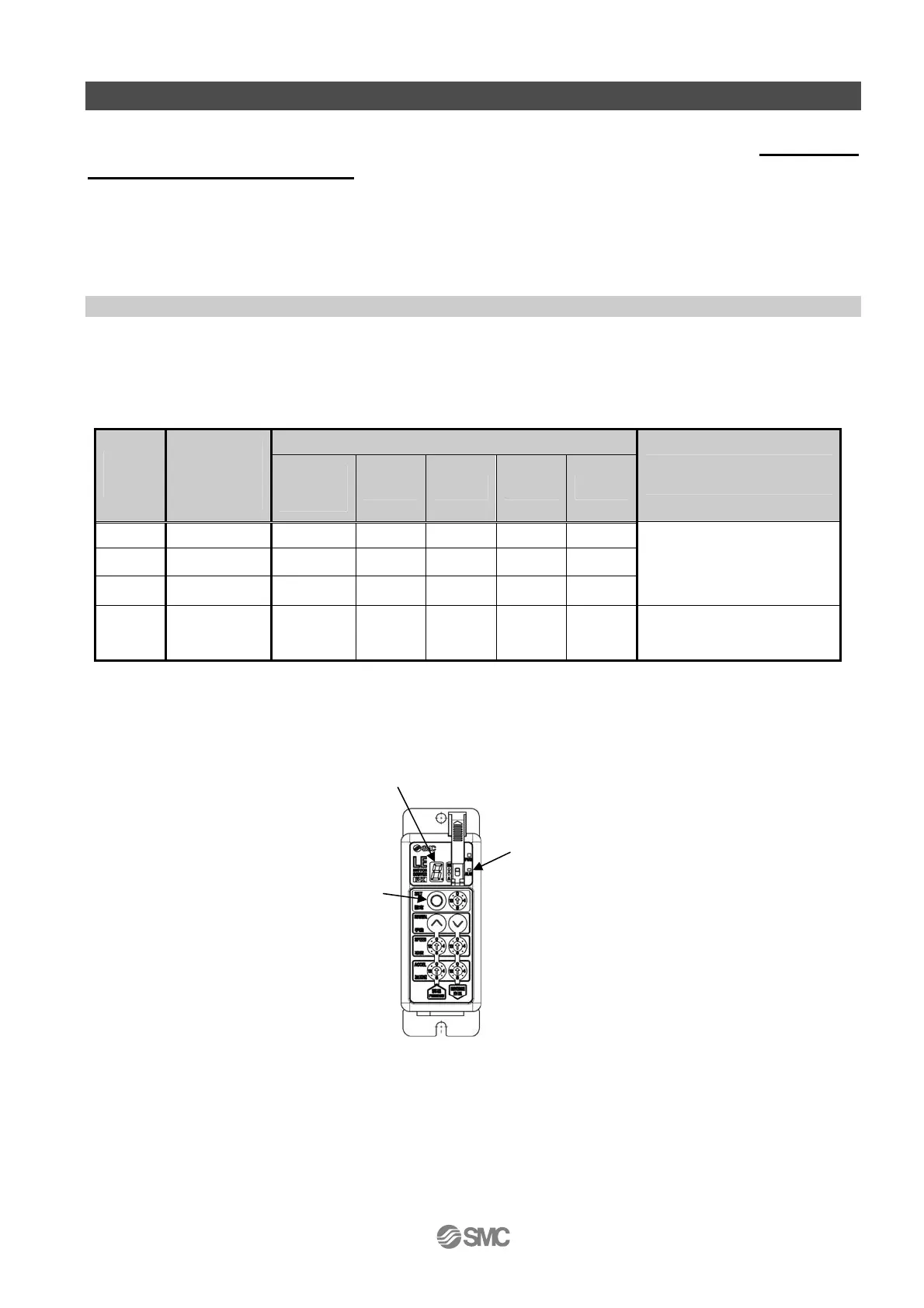
12.1 Alarm group output
Alarms from this controller are output to the LED and the signal is output from I/O so that the alarm
type is recognizable. For alarms, LED
○
b lights up in red and the alarm group is indicated by the
7-segment LED
○
f . The I/O indicates the presence of an alarm ALARM with OUT0 to 3.
Parallel signal output
Alarm
group
7-segment
LED
Display
ALARM
*1,2
OUT0 OUT1 OUT2 OUT3
How to restart the
operation
B
b
OFF OFF ON OFF OFF
C
c
OFF OFF OFF ON OFF
D
d
OFF OFF OFF OFF ON
Input RESET or set the
button
○
g
E E OFF OFF OFF OFF OFF
Power supply for control is
turned off --> Supply again
*1 ALARM is OFF when an alarm is generated 1 because it is a normal closed type.
*2 When the servo is turned OFF, ALARM is turned OFF. The generated alarm cannot be identified
only by OUT5.
○
g
○
b
○
f

 Loading...


