錯誤! 尚未定義樣式。
13
SMC8014WN and SMC8014WN2 Wireless Cable Modem Gateway Administrator Manual
SMC8014WN2 Front and Rear panels
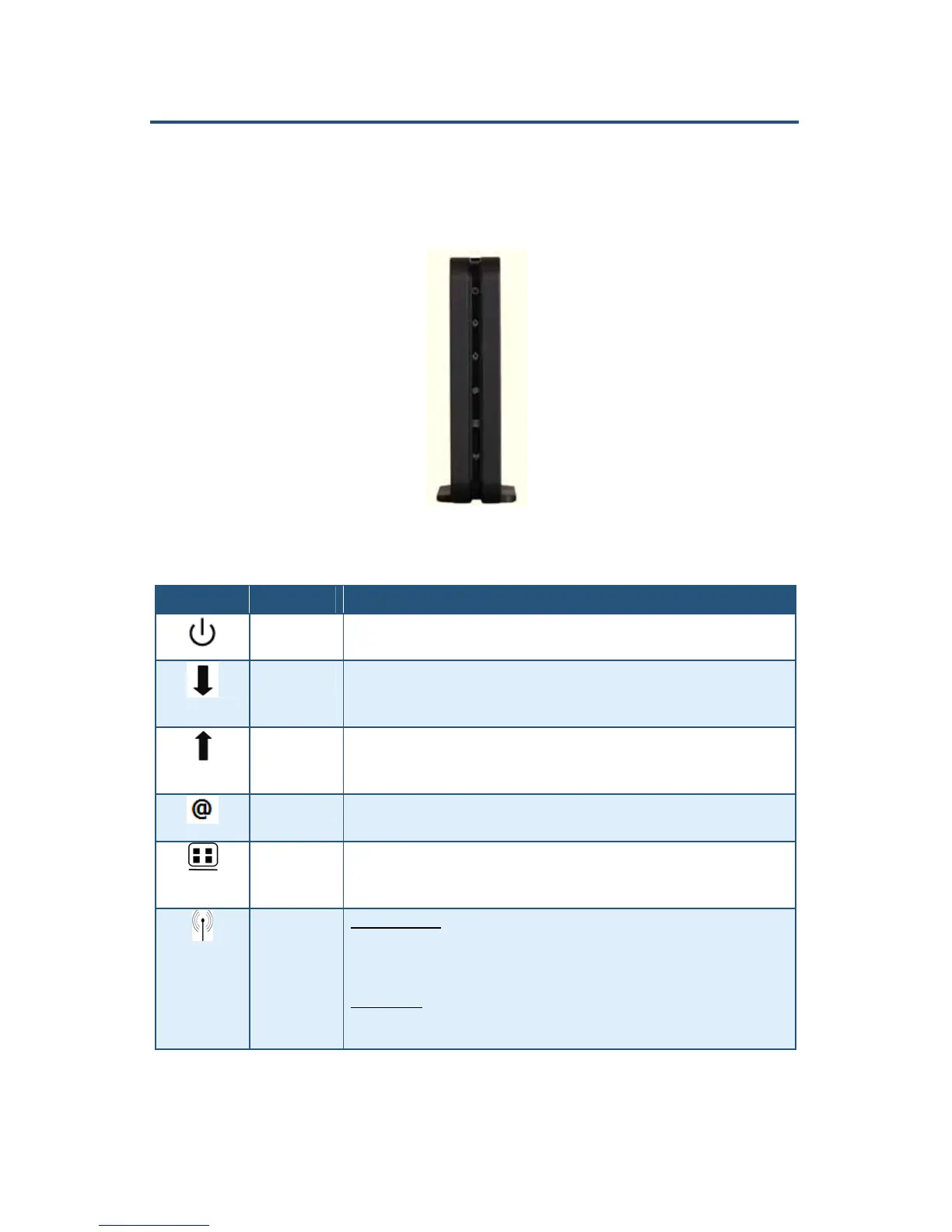
The front panel of the SMC8014WN2 Wireless Cable Modem Gateway contains a set of
light-emitting diode (LED) indicators that show the status of the Gateway and simplify
troubleshooting. Figure 3 shows the front panel LEDs and Table 3 describes the them.
Figure 3. Front Panel of the SMC8014WN2 Wireless Cable Modem Gateway
Table 3. SMC8014WN2 Front Panel LEDs
Icon Icon Name Description
Power Green = power is supplied to the Gateway.
OFF = power is not supplied to the Gateway.
DS Green Flashing =-attempt to connect to downstream frequency.
Green On = Gateway is connected to downstream frequency.
OFF = not scanning.
US Green Flashing= attempt to connect upstream frequency
Green ON = Gateway is connected to upstream frequency.
OFF = not scanning.
Status Green ON = cable modem has finished CMTS registration.
Green Flashing = cable modem is attempting to register with CMTS.
LAN Green ON = connected at 10 Mbps or 100 Mbps
Green Flashing = data is transmitting.
OFF = no Ethernet link is detected.
WLAN/WPS Wireless Function
Green ON = wireless interface is enabled.
Green Flashing= data is transmitting.
OFF = wireless interface is disabled.
WPS Function
Green and Red dual colors LED generate WPS LED behavior . Disable WLAN control ability
to avoid WPS LED behavior if LED works as WPS function.