ACM1_TAU_UserManual_En
Page 17 of 35
SME s.p.a. Via della Tecnica 40 Z.I.
36071 ARZIGNANO (VI) ITALY
Phone +39 0444 470511 - Fax +39 0444 451803
info@grupposme.com - www.grupposme.com
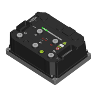
3.2 Power Terminals
Wiring
The Controller has five Power Terminals, which are clearly marked on Controller’s body as B+, B-,
U, V, W (figure 4).
Power Terminals on Controller
Positive Battery coming from the Main Contactor
The recommended screw torque for fixing the Power Terminals is 6.4 Nm. This value is reported
on the label placed on the cover, exceeding the recommended value may cause damages.
Sizing
The environment conditions strongly affect the current carrying capacity of a single wire.
Temperature and wire length can decrease the cable performance and other factors such as
Controller duty cycles and airflow should also be taken into consideration when sizing the power
cables.
The following formula gives an advice on the cable size needed in welding cable, not grouped with
other cables:
Ambient Temperature = 25°C
Maximum Temperature rise on the cable surface = 60°C
Suggested Current Density [A
rms
/mm
2
] = 5 A
rms
/mm
2