EasyManuals Logo
Home>SME>Controller>AC-M1

SME AC-M1 User Manual

Default Icon
35 pages
To Next Page IconTo Next Page
To Previous Page IconTo Previous Page
Page #9 background imageLoading...
Page #9 background image
ACM1_TAU_UserManual_En
Page 9 of 35
SME s.p.a. Via della Tecnica 40 Z.I.
36071 ARZIGNANO (VI) ITALY
Phone +39 0444 470511 - Fax +39 0444 451803
info@grupposme.com - www.grupposme.com
2.3.2 Signal: Inputs and Outputs
Digital Inputs: 19
Analog Inputs: 6
Digital Outputs (ON/OFF): 2
Driver Outputs (PWM): 3
Motor Speed Sensor Inputs: 2 (A+B Channels)
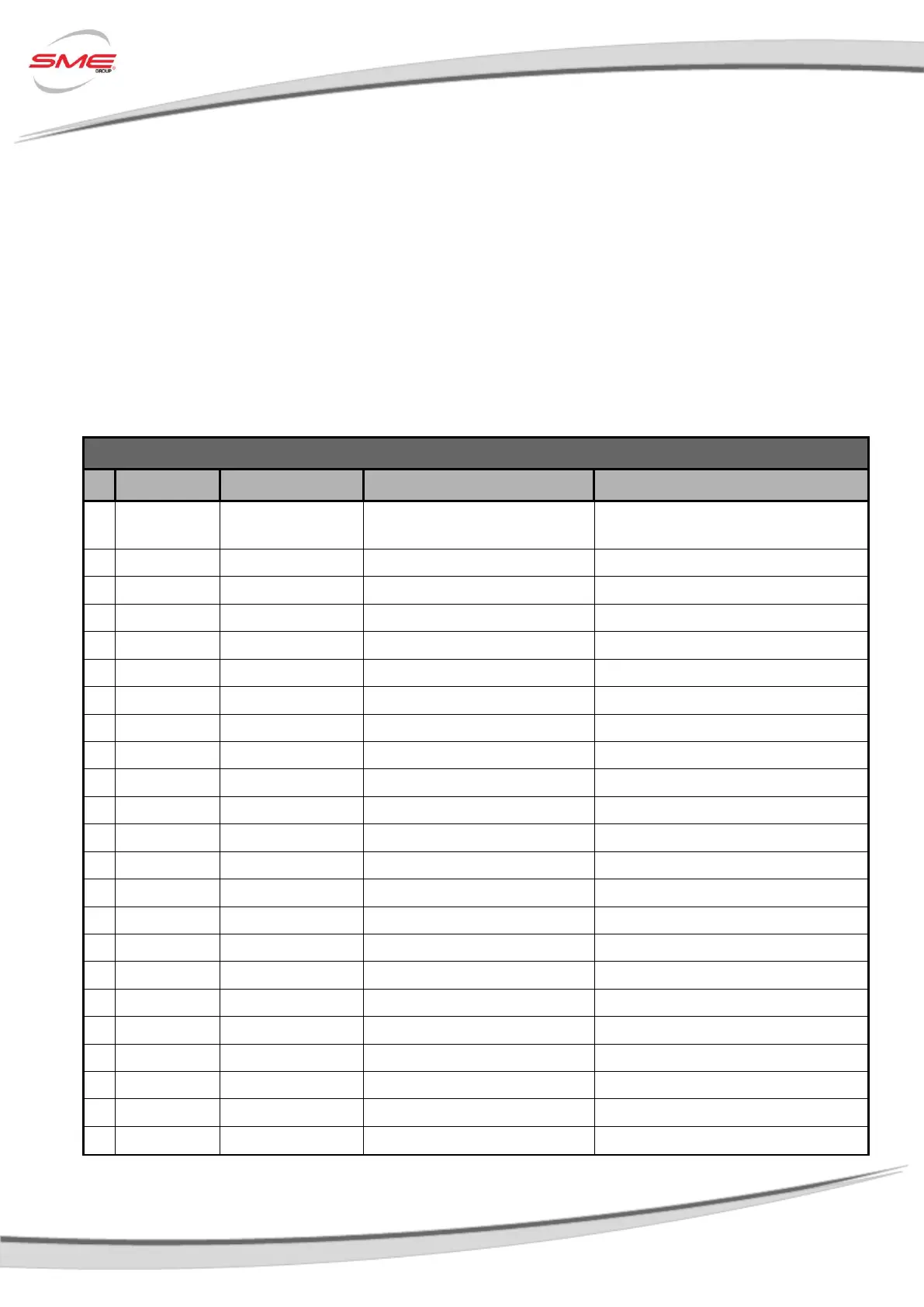
Refer to following tables for a complete AC-M1 controller K1 and K2 connectors pin-out.
K1 connector pin-out for AC-M1 SPECIFICATIONS
Pin
Name
I/O
Specification
Typical Function
1
KEY SWITCH IN
Supply Input
Rated battery +25/-30%, 6Amax
Positive supply of the control section of
the AC-M1
2
DIGITAL IN 1
Digital Input
4mA pull-up, VL<=1V, VH>=3,5V
TO BE ASSIGNED
3
DIGITAL IN 2
Digital Input
4mA pull-up, VL<=1V, VH>=3,5V
TO BE ASSIGNED
4
DIGITAL IN 3
Digital Input
4mA pull-up, VL<=1V, VH>=3,5V
TO BE ASSIGNED
5
DIGITAL IN 4
Digital Input
4mA pull-up, VL<=1V, VH>=3,5V
TO BE ASSIGNED
6
DIGITAL IN 5
Digital Input
4mA pull-up, VL<=1V, VH>=3,5V
TO BE ASSIGNED
7
DIGITAL IN 6
Digital Input
4mA pull-up, VL<=1V, VH>=3,5V
TO BE ASSIGNED
8
DIGITAL OUT 1
Digital Output
Low side 0,5A
TO BE ASSIGNED
9
COIL RETURN
Supply Output
High side 5A max
Positive common
10
RS-232 RX
Com Input
-
Serial port
11
RS-232 TX
Com Output
-
Serial port
12
DIGITAL IN 7
Digital Input
4mA pull-up, VL<=1V, VH>=3,5V
TO BE ASSIGNED
13
DIGITAL IN 8
Digital Input
4mA pull-up, VL<=1V, VH>=3,5V
TO BE ASSIGNED
14
LIN IN/OUT
Com Input/Output
12mA pull-up
LIN display connection
15
CAN-H
Com Input/Output
CAN-bus
CAN H (No internal termination resistor)
16
DRIVER OUT 1
PWM Output
Low side 2A
TO BE ASSIGNED
17
DRIVER OUT 2
PWM Output
Low side 1,5A
TO BE ASSIGNED
18
I/O GROUND
-
-
Negative logic supply
19
DIGITAL OUT 2
Digital Output
Low side 1,5A
TO BE ASSIGNED
20
DRIVER OUT 3
PWM Output
Low side 1,5A (*)
TO BE ASSIGNED
21
+12V OUT
Supply Output
12V 300mAmax
12V supply
22
CAN GROUND
-
-
CAN- bus negative supply
23
CAN-L
Com Input/Output
CAN-bus
CAN L (No internal termination resistor)

Other manuals for SME AC-M1

Questions and Answers:

Question and Answer IconNeed help?

Do you have a question about the SME AC-M1 and is the answer not in the manual?

SME AC-M1 Specifications

General IconGeneral
BrandSME
ModelAC-M1
CategoryController
LanguageEnglish

Related product manuals