EasyManuals Logo
Home>Snapper>Lawn Mower>1650 Series

Snapper 1650 Series User Manual

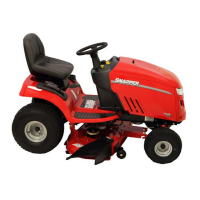
Snapper 1650 Series
64 pages
To Next Page IconTo Next Page
To Previous Page IconTo Previous Page
Page #4 background imageLoading...
Page #4 background image
SEAT
&
SEAT
RAILS
If
the
operators
seat
has
to
be
replaced
simply
tilt
it
forward
and
remove
the
four
flange
lock
bolts
securing
the
seat
to
the
hinge
frame
assembly,
install
the
replace¬
ment
seat
and
secure
with
the
same
hard¬
ware.
If
seat
rail
replacement
is
required,
proceed
as
follows:
STEP
1:
Separate
the
seat
from
the
fender
by
removing
one
of
the
retaining
rings
from
the
end
of
the
seat
pivot
pin
then
pull
the
pin
and
remove
the
seat.
STEP
2:
Remove
the
two
bolts
securing
each
rail
to
the
fender
and
the
bolt
at
front
secur¬
ing
the
seat
pivot
frame
to
the
rail.
Replace
the
rail
or
rails
and
reverse
the
foregoing
procedure
to
reassemble
the
components.
FIG.
1.4
-
FENDER
&
SEAT
ASSEMBLY
DETAIL-1650
&
1855
SERIES
INSTRUMENT
(DASH
COWL)
PANEL
The
steering
wheel
must
be
pulled
to
re¬
place
the
instrument
panel.
Refer
to
section
two
for
steering
wheel
removal
procedure.
After
pulling
the
steering
wheel,
lift
the
hood
and
proceed
as
follows
to
replace
the
instru¬
ment
panel.
STEP
1:
Disconnect
and
remove
the
ammeter
and
hourmeter
if
so
equipped.
STEP
2:
Disconnect
throttle
and
choke
cables
and
pull
cables
out
of
the
panel.
STEP
3:
Remove
retaining
nuts
from
the
choke,
ignition
and
PTO
switches.
Turn
the
knob
off
the
speed
control
lever.
STEP
4:
Use
a
phillips
head
screwdriver
to
re¬
move
the
four
screws
securing
the
panel
to
the
pedestal
frame
then
remove
the
panel.
Reverse
the
foregoing
procedure
to
install
the
replacement
panel
and
to
reassemble
the
instruments
and
controls.
FIG.
1.5
-
INSTRUMENT
PANEL
DETAIL
1.
AMMETER
4.
IGNITION
2.
PTO
SWITCH
5.
THROTTLE
3.
CHOKE
6.
HOURMETER
(OPTION)
HOOD
&
GRILLE
Tilting
the
hood
full
forward
usually
pro¬
vides
sufficient
access
for
most
front
area
works,
however,
it
is
easily
from
the
tractor
as
follows:
STEP
1:
Tilt
the
hood
assembly
forward
and
unplug
the
headlight
wires
at
the
terminals.
STEP
2:
Tilt
the
hood
backward
enough
to
take
tension
off
the
stop
cable,
then
pull
the
hair
pin
from
the
clip
and
disconnect
the
cable.
STEP
3:
With
the
hood
tilted
forward,
lift
up¬
ward
and
pull
forward
until
the
tilt
hinges
on
both
sides
clear
the
slots
in
the
frame
front
cross
member.
STEP
4:
If
the
grille
is
to
be
removed,
turn
the
flange
locknuts
off
the
seven
studs
welded
to
the
forward
edges
of
the
hood.
Disengage
the
studs
from
the
grille
tabs
and
separate
these
items.
The
screen
can
now
be
removed
from
the
inside
of
the
grille
if
required.
Reverse
the
foregoing
procedure
to
reassem¬
ble
and
reinstall
hood
components.
FIG.
1.6-
ACCESS
WITH
HOOD
FORWARD
1.2
f

Other manuals for Snapper 1650 Series

Questions and Answers:

Question and Answer IconNeed help?

Do you have a question about the Snapper 1650 Series and is the answer not in the manual?

Snapper 1650 Series Specifications

General IconGeneral
BrandSnapper
Model1650 Series
CategoryLawn Mower
LanguageEnglish

Related product manuals