15
EN
Type Terminal no.
Status of
thecontact
Description
Output
characteristics
Recommended
connection
cross-section
Auxiliary contact
block
1309 0001
11/12/14
11
14
12
Changeover switch in position I
250V AC 5A AC1
30 Vdc 5 A
0.5 to 2.5 mm²
(rigid)
0.5 to 1.5 mm²
(stranded)
21/22/24
21
24
22
Changeover switch in position II
250V AC 5A AC1
30 Vdc 5 A
01/02/04
01
04
02
Changeover switch in position 0
250V AC 5A AC1
30 Vdc 5 A
Auxiliary contact
block
1309 0011
11/12/14
11
14
12
21
24
22
01
04
02
Changeover switch in position I
250V AC 5A AC1
30 Vdc 5 A
21/22/24 Changeover switch in position II
250V AC 5A AC1
30 Vdc 5 A
01/02/04
Changeover switch in position 0
250V AC 5A AC1
30 Vdc 5 A
207 208 209 210
63 64 73 74
2 4 6
8
1 3 5 7
2 4 6
8
1 3 5 7
2 4 6 8
1 3 5 7
2 4 6 8
1 3 5 7
/
I1 I2 I3
O1 O2
LOAD
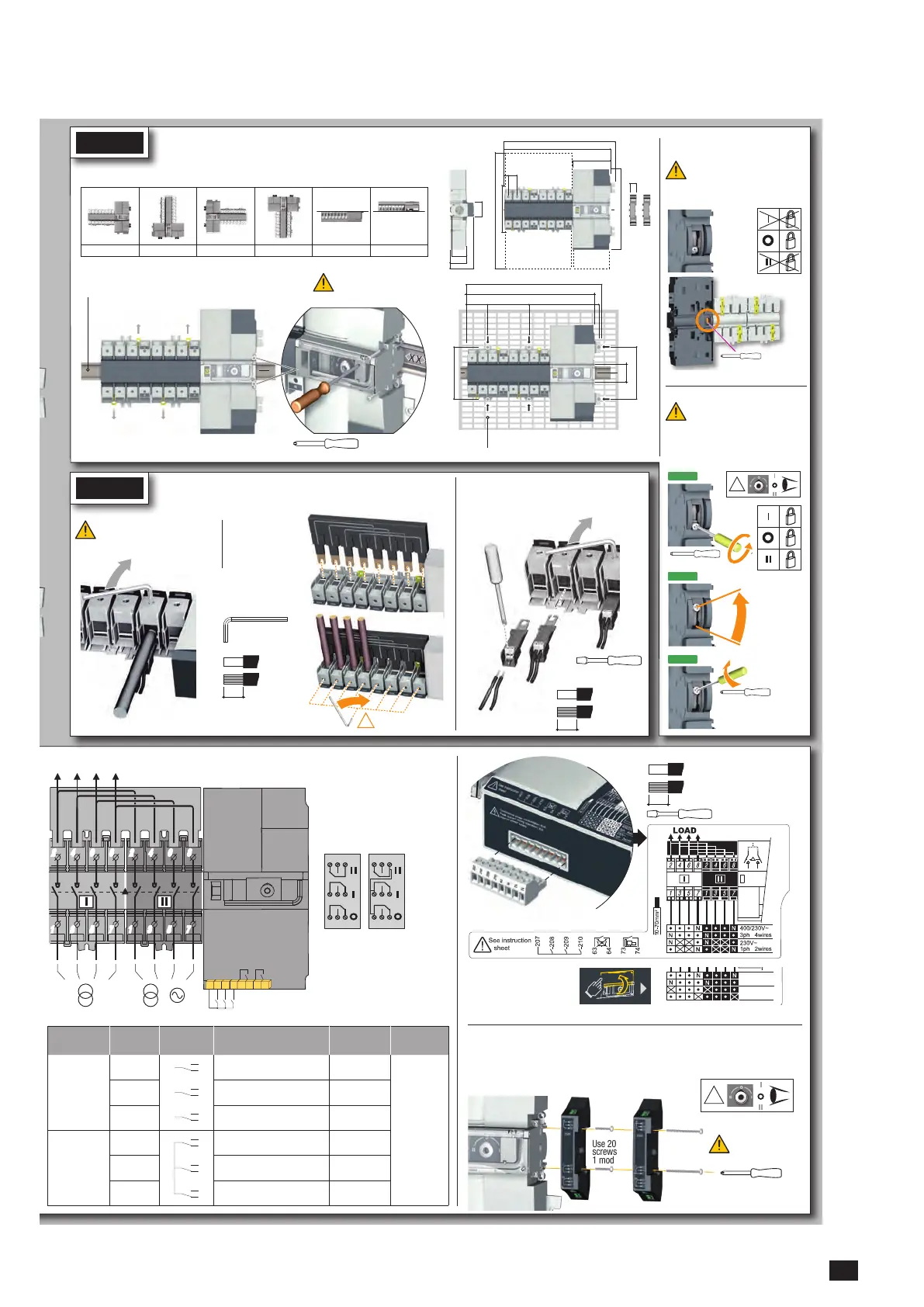
Ensure that the product is in
Manual Mode (front cover
open).
230/127V~
3ph 4wires
230/127V~
3ph 3wires
Slotted head 3mm 0,5 Nm
0,5 to 2,5 mm²
0,5 to 1,5 mm²
6 mm
5 A AC1
250 Vac
22 24 21
11 14 12
01 04 02
1309 0001
5 A AC1
250 Vac
22 24 21
11 14 12
01 04 02
1309 0011
Pozidriv PZ2 - 1 Nm
Use 20mm
screws for
1 module
Use 35mm
screws for
2 modules
!
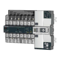
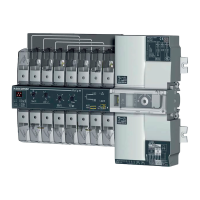
Auxiliary contacts: Fitting of auxiliary contacts: 1309 0001 or 1309 0011
To fit an AC, the switch must first be put in position 0. An auxiliary contact module comprises: one NO/
NC changeover contact for each position (I-0-II). To install use the long screws supplied with the module.
STEP 1
The ATyS M is delivered with
padlocking configured to the
O position.
To allow padlocking in all
positions (I - O - II), configure
the ATySM as follows before
installation. (Screw is located
at the back of the product).
STEP 3
Posidriv PZ2
2,2 lb-in 0,25 Nm
Posidriv PZ2
Posidriv PZ2
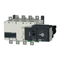
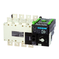
Installation
Padlocking configuration
Caution: Ensure that the product is installed on a flat rigid surface.
53
46
73,5
45
340
326
131,5
131,5
52 104 176
47
Recommended orientation
Recommended Ok Ok Ok Ok Ok
Posidriv PZ1
1 Nm
Tighten to avoid
movementonthe DINrail.
DIN RAIL
IEC 60715
6 mounting brackets
6x M6 screw - 2,5 Nm
2x
2x
STEP 2
Power Terminal Connections
Source supply side
Hexagonal Metric
Allen size 4
5,0 Nm
It is essential to tighten all used
terminals, with cables and/or
bridging bars, before use.
Hexagonal Metric
"
AWG
10 to 70 mm
2
6 to 70 mm
2
*
AWG
!
X8
Voltage taps provide 2x ≤ 1.5mm
2
connections.
They can be fitted in any terminals on the source
supply side. Do not use on the load side when
equipped with a bridging bar.
Load side
bridging bar.
125A: 1309 4006
160A: 1309 4016
Slotted head 3,5 mm
0,45 Nm
0,5 to 2,5 mm²
0,5 to 1,5 mm²
6 mm
10 to
70 mm²
15mm
MAX : 2
340
26
116
245
143
350
18
13
324
!
Step 1
Step 2
Step 3
 Loading...