32
EN
11.
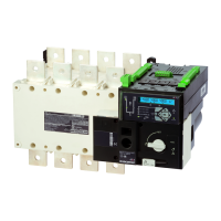
is delivered in the 0 position.
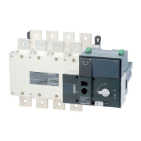
2 4 6
8
1
3
5 7
2 4 6 8
1 3 5 7
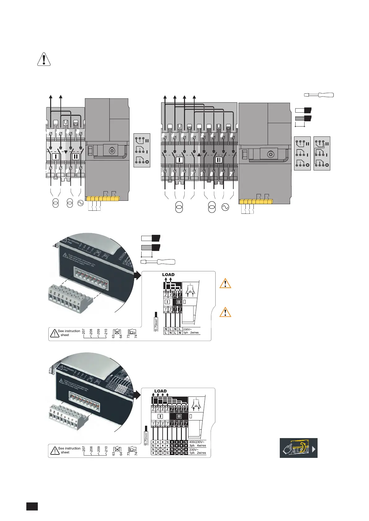
207 208 209 210
63 64 73 74
/
I1 I2 I3
O1 O2
LOAD SIDE LOAD SIDE
SI
SI
SII
SII
Slotted head 3,5 mm
0,45 Nm
0,5 to 2,5 mm²
0,5 to 1,5 mm²
6 mm
207 208 209 210
63 64 73 74
2 4 6
8
1
3
5 7
2 4 6
8
1
3
5 7
2 4 6 8
1 3 5 7
2 4 6 8
1 3 5 7
/
I1 I2 I3
O1 O2
5 A AC1
250 Vac
22 24 21
11 14 12
01 04 02
1309 0001
5 A AC1
250 Vac
22 24 21
11 14 12
01 04 02
1309 0001
5 A AC1
250 Vac
22 24 21
11 14 12
01 04 02
1309 0011
All pressure on the connector pins is to be
Source must always be connected as
Slotted head 3mm 0,5 Nm
0,5 to 2,5 mm²
0,5 to 1,5 mm²
6 mm
Ensure that the product is in
Manual Mode (front cover
open).
 Loading...