31
EN
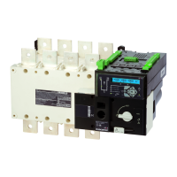
10.3.4.2.
Step 1
Step 2
Neutral must be connected as shown in the
drawing above in section «10.3.4.1. Auto-
transformer connections», page 30
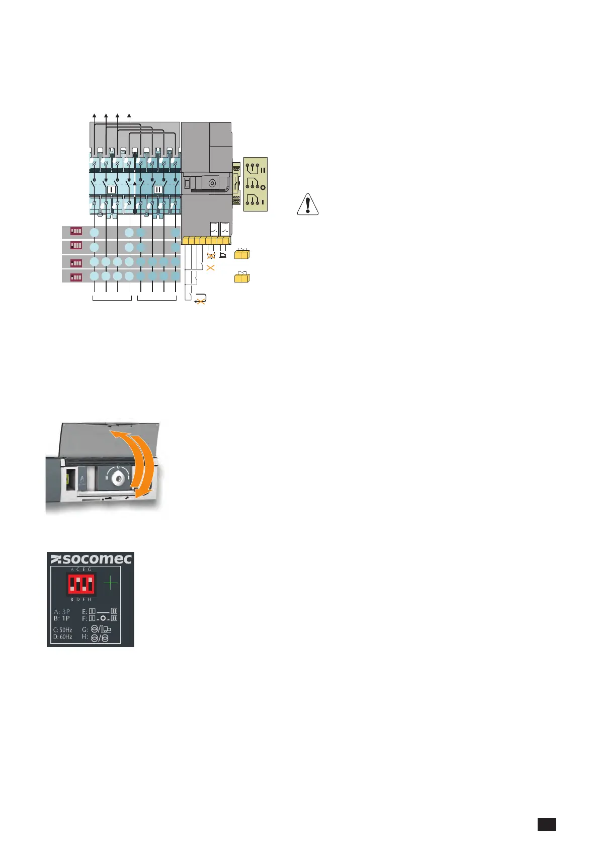
1P
B
B
1P
3P
A
3P
A
N
L1 L2 L3
L1 L2 L3
N
N
L1 L2 L3
L1
L2 L3
N
N
L1
L1
N
N
L1
L1
N
TEST
/ PRIORITY
AUT
63 64
73 74
207 208 209 210 63 64 73 74
2A 30Vdc
1A 125Vac
0,5A 230Vac
resistive
max 60W or 250VA
2A 30Vdc
1A 125Vac
0,5A 230Vac
resistive
max 60W or 250VA
START
STOP
OK
NOK
2 4 6
8
1
3
5 7
2 4 6
8
1
3
5 7
2 4 6 8
1 3 5 7
2 4 6 8
1 3 5 7
AUT
5 A AC1
250 Vac
12 14 11
21 24 22
01 04 02
Load
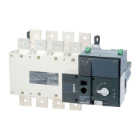
10.3.4.3. Reset of neutral position
Step 1
Step 2
Step 3
Step 4
End of the procedure for detecting the neutral position.
 Loading...