Chapter 2: Installing the SolarEdge Firefighter Gateway
Firefighter Gateway Installation Guide MAN-01-00113-1.2
2 Hook the two lower clips of the SolarEdge gateway onto the lower edge of the DIN rail.
3 Press the SolarEdge gateway upwards and snap it into the upper edge of the DIN rail. When on the
rail, the clip "grips" the rail on both the top and bottom lips of the rail.
To remove the DIN clip from the rail, simply push upwards on the DIN clip (thereby compressing the
springs in the bottom), pivot the top of the clip off of the rail, and then move the whole clip down to
also release the bottom of the clip. No screwdrivers or special tools are required.
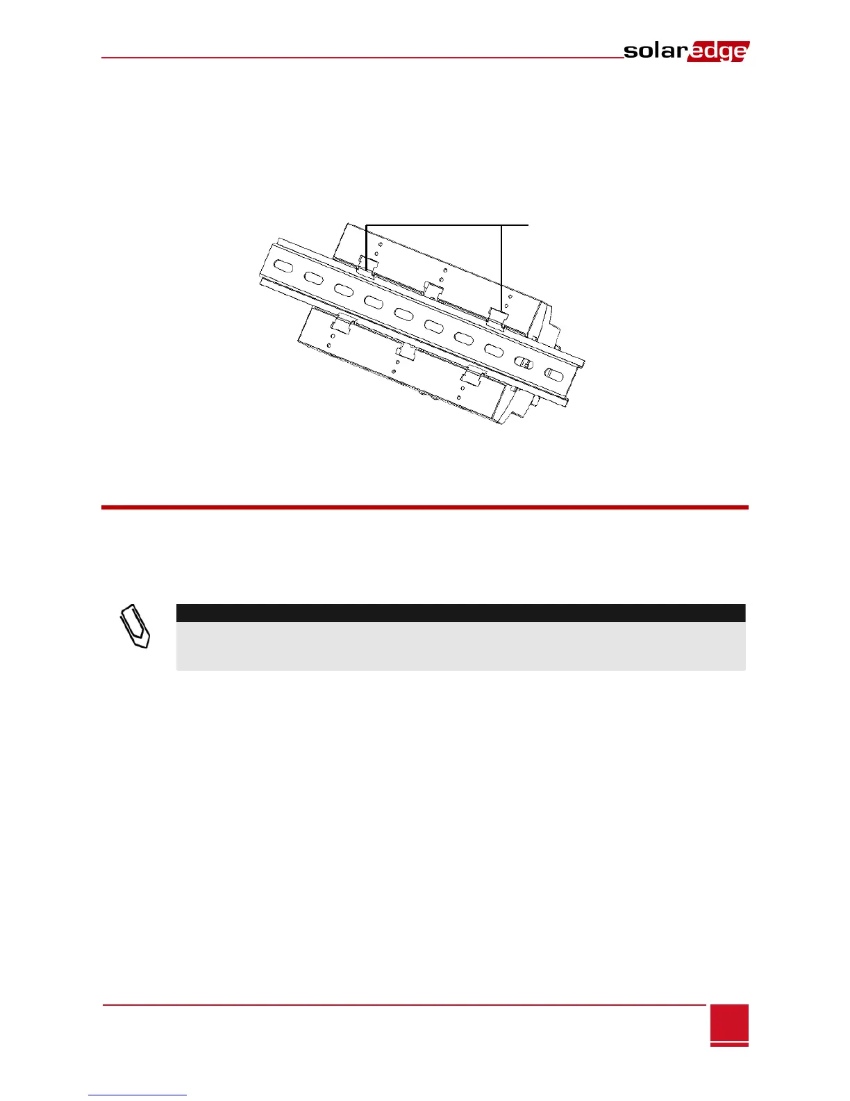
4 The following figure shows the gateway’s rear side when mounted on a DIN rail.
Figure 6: Gateway Mounted on a DIN Rail
Connecting the Firefighter Gateway to AC
For connecting to power, use the supplied power supply:
1 Insert the power supply DC connector to the SolarEdge gateway (see Figure 3).
2 Connect the power supply to the AC mains. The LEDs are lit momentarily to indicate power
connection (see Figure 3)
If you use a non-SolarEdge power supply, check that it has 12Vdc/1A output ratings, and that it is
certified to UL/CSA/IEC60950-1 2ed standards. Limited Power Source output, NEC class 2.
Verify the power supply polarity as marked on the gateway.
 Loading...