Chapter 4: Connecting the Firefighter Gateway to the SolarEdge Installation
Firefighter Gateway Installation Guide MAN-01-00113-1.2
Chapter 4: Connecting the Firefighter
Gateway to the SolarEdge Installation
Overview
The SolarEdge firefighter gateway connects to the PV system installation using the RS485 communication
option. The RS485 option enables creating a chain (bus) of up to 31 slave SolarEdge devices, connected to
one master, which can be another SolarEdge device or the SolarEdge firefighter gateway.
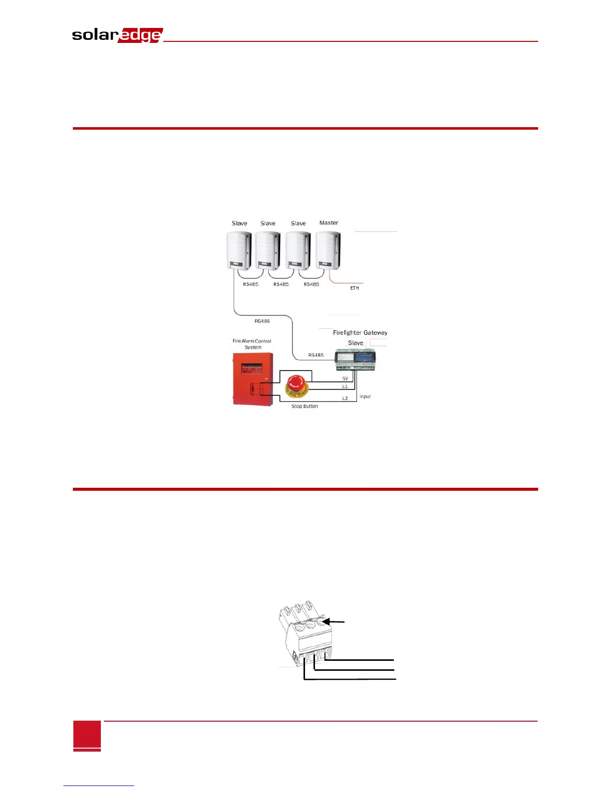
The following is an example of a slave gateway connected to a chain of slave inverters (one inverter is the
master).
Figure 10: Example of RS485 Connection
The following sections describe how to connect the RS485 bus and how to configure its components.
Connecting and Configuring the RS485
The RS485 bus uses a three-wire cable connecting the RS485-1/2 terminal blocks on the SolarEdge
gateway to the RS485 input of the inverters/SMI.
► To connect the RS485 communication bus between inverters/SMIs and
SolarEdge gateway:
1 Use one of the supplied 3-pin terminal blocks: Loosen the screws and insert the wire ends into the
A, B and G pins. For connections longer then 10m use twisted pair wires for A and B wires.
Figure 11: 3-pin Terminal Block
 Loading...