There are two types of contact states in Emergency Stop buttons/relays:
Normally open (NO) – the contacts are open until closed by operation of the switch. This type of
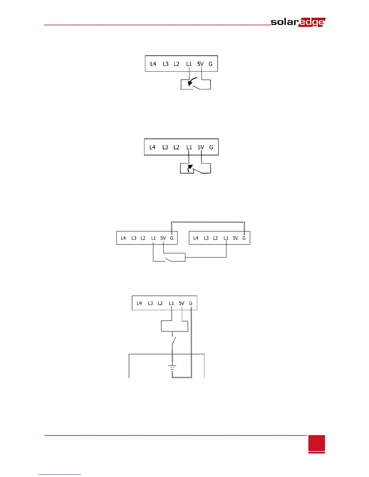
switch should be connected in the following manner:
This installation is safe when L1/L2 has 5V input, and active with L1/L2 is not connected. This is
considered Normal polarity in the configuration screen.
Normally closed (NC) – the contacts are closed until opened by operation of the switch. This type of
switch should be connected in the following manner:
This installation is safe when L1/L2 is not connected and active when L1/L2 is 5V. This is considered
Reverse polarity in the configuration screen.
If you connect more than one firefighter gateways to the same emergency stop button, they should
connect to the same grounding, as in the following example:
In some fire alarm control systems, the switch is grounded internally. This type of switch should be
connected in the following manner, sharing ground between the control system and the firefighter
gateway.
In these cases, a Normally Open relay will connect L1/L2 to ground for safety, and when active, L1/L2
is 5V. This will be configured as a reverse polarity switch.
 Loading...