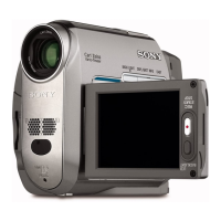
6-26
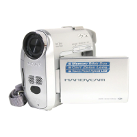
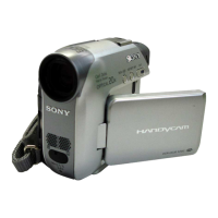
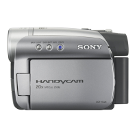
DCR-HC39E/HC41/HC42/HC42E/HC43/HC43E
5. Flange Back and Zoom Lever Center Adjustment
(Using the flange back adjustment chart and
subject more than 500 m away)
The inner focus lens flange back adjustment is carried out auto-
matically. In whichever case, the focus will be deviated during
auto focusing/manual focusing.
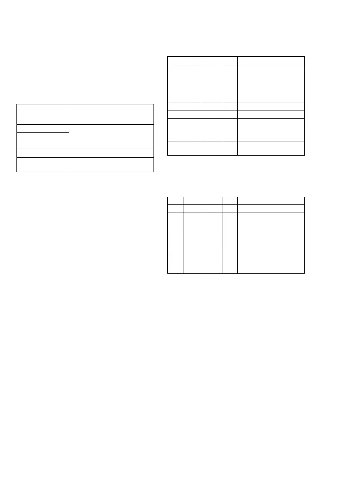
5-1. Flange Back Adjustment (1)
RadarW
RadarW
RadarW
Subject
Flange back adjustment chart
(2.0 m from the front of lens)
(Luminance: 300 to 400 lux)
Measurement Point Adjusting remote commander
Measuring Instrument
Adjustment Page F
Adjustment Address 11, 48 to 58
Specified value
Data of page: F, address: 57 is “00” to “0B”
Data of pege: 6, address: 0C is “00”
Note 1: Perform “HALL Adjustment” and “MR Adjustment”
before this adjustment.
Note 2: Perform the adjustment with the lens in horizontal state.
Note 3: Check that the data of page: 0, address: 10 is “00”.
Note 4: Check that the data of page: 6, address: 02 is “00”. If
not, select page: 6, address: 01, set data: 00, and press
PAUSE button.
Note 5: Don't touch the zoom lever during adjustment.
Switch setting
1) POWER............................................. CAMERA-TAPE mode
2) NIGHTSHOT PLUS ........................................................ OFF
3) COLOR SLOW S (Menu setting) ................................... OFF
Preparations before adjustments:
1) Check that the center of Flange back adjustment chart meets
the center of shot image screen with the zoom lens at TELE
end and WIDE end respectively.
Adjusting method:
Order Page Address Data Procedure
10 0101
2E FD
Set the bit value of bit4 is
“1”, and press PAUSE
button. (Note 6)
36 01 13 Press PAUSE button.
4Wait for 2 seconds.
56 01 15 Press PAUSE button. (Note 7)
66 02
Check the data changes to
“01”.
76 0C Check the data is “00”.
8F 57
Check the data is “00” to
“0B”.
Note 6: For the bit values, refer to “6-4. SERVICE MODE”, “4-
3. 3. Bit value discrimination”.
Note 7: The adjustment data will be automatically input to page:
F, address: 11, 48 to 58.
Processing after Completing Adjustment:
Order Page Address Data Procedure
16 01 00 Press PAUSE button.
26 01 25 Press PAUSE button.
36 01 00 Press PAUSE button.
4E FD
Set the bit value of bit4 is
“0”, and press PAUSE
button. (Note 6)
50 0100
6
Perform “Flange Back
Adjustment (2)”.
 Loading...