6-46
DCR-HC39E/HC41/HC42/HC42E/HC43/HC43E
3-2. SYSTEM CONTROL SYSTEM ADJUSTMENTS
1. Initialization of 8, A, B, C, D, E, F, 14, 18, 19, 1A, 1B,
1C, 1E, 1F Page Data
If the 8, A, B, C, D, E, F, 14, 18, 19, 1A, 1B, 1C, 1E, 1F page data
is erased due to some reason, perform “1-2. INITIALIZATION
OF 8, A, B, C, D, E, F, 14, 18, 19, 1A, 1B, 1C, 1E, 1F PAGE
DATA” of “CAMERA SYSTEM ADJUSTMENTS”.
Check that the data of page: 0, address: 10 is “00”.
If not, select page: 0, address: 10, and set the data “00”.
2. Touch Panel Adjustment
Adjust the calibration of touch panel.
Mode VTR stop (PLAY/EDIT mode)
Signal Arbitrary
Adjustment Page A
Adjustment Address 90 to 93
Note 1: This adjustment should be carried out upon completetion
of the LCD system adjustments.
Note 2: Check that the data of page: 0, address: 10 is “00”.
Note 3: Check that a Memory Stick Duo is not insteted.
Note 4: Check that the LCD panel is not reverse mode.
Note 5: Adjustment must be performed while observing the LCD
screen from the front.
Preparation:
Order Page Address Data Procedure
15 0101
25 0500
35 06C7
45 0700
55 0800
65 0900
75 0AFF
85 0B00
95 0C00
10 5 0D 00
11 5 0E 01
12 5 00 01 Press PAUSE button.
13
Check that the touch panel
adjustment screen is
displayed.
14 Perform “Adjusting method”.
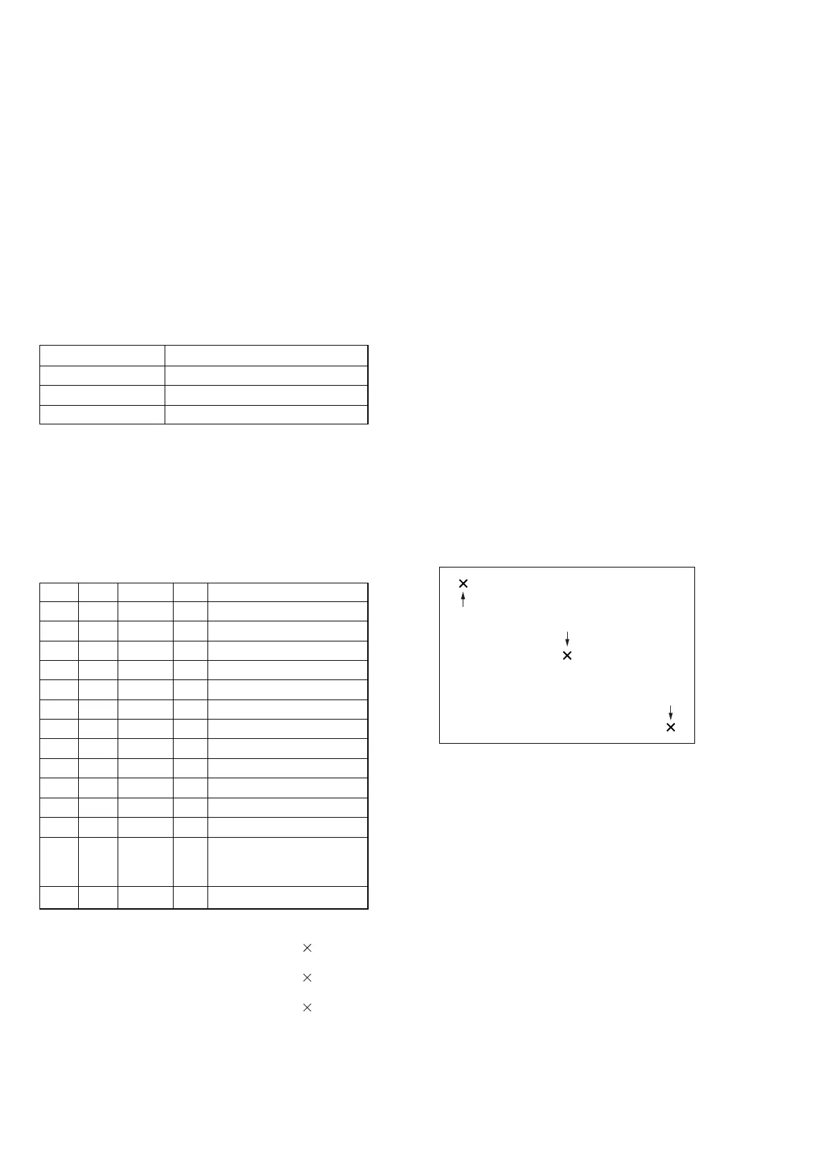
Adjusting method:
1) Using a ball-point pen etc., push the center of “ ” indicated
in the part A.
2) Using a ball-point pen etc., push the center of “ ” indicated
in the part B.
3) Using a ball-point pen etc., push the center of “ ” indicated
in the part C.
A
C
B
Fig. 6-3-3