 Loading...
Do you have a question about the Sony DSC-H10 and is the answer not in the manual?
| Sensor Type | Super HAD CCD |
|---|---|
| Effective Pixels | 8.1 Megapixels |
| Optical Zoom | 10x |
| Digital Zoom | 2x |
| LCD Screen Size | 3.0 inches |
| Image Stabilization | Optical |
| Camera Type | Compact |
| Sensor Size | 1/2.5 inch |
| Aperture Range | f/3.5-4.4 |
| LCD Screen Resolution | 230, 000 pixels |
| Video Resolution | 640 x 480 |
| Battery Type | NP-BG1 |
| Focal Length | 38-380 mm (35mm equivalent) |
| Shutter Speed | 1/2000 sec |
| Storage Media | Memory Stick Duo / Memory Stick PRO Duo |
| ISO Sensitivity | ISO 100-3200 |
Details on camera system, lens, exposure control, white balance, file formats, and recording media.
Information on power sources, battery charger, rechargeable battery pack, and general operational specifications.
Steps to perform safety checks after service before releasing the unit to the customer.
Identifies critical safety components requiring specific replacement parts and handling.
Guidance on destination data and USB serial number input after SY-210 board replacement.
Explanation of the self-diagnosis function and how it displays errors.
A table listing self-diagnosis codes, symptoms, and corresponding correction procedures.
Procedures for initializing flash error codes and managing internal memory data.
Steps to enable and perform data writing to the camera's internal memory.
General repair notes and procedure for safely discharging the charging capacitor.
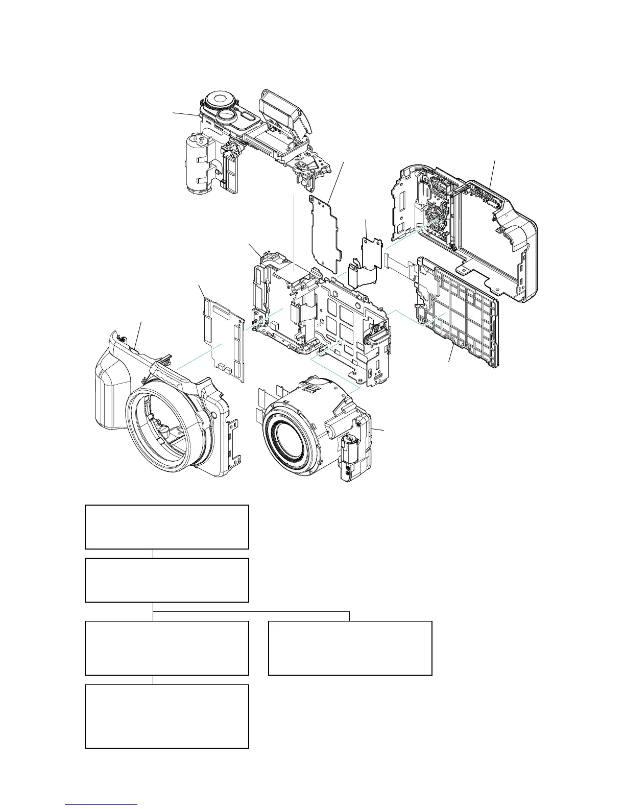
Lists major components and their locations within the camera structure.
Provides a structured flow for disassembling various sections of the camera.
Detailed steps for disassembling the front cabinet section of the camera.
Detailed steps for disassembling the rear cabinet section of the camera.
Detailed steps for disassembling the upper cabinet section of the camera.
Steps for disassembling and removing components from the main board.
Steps for disassembling and removing components from the BT holder section.
Illustrations and instructions for attaching various insulating sheets.
Detailed method for attaching the FL-179 flexible board to the camera assembly.
Detailed method for attaching the PL-048 flexible board to the camera assembly.
Introduction to the overall and power block diagrams for the service manual.
The first part of the overall block diagram illustrating system connections.
The second part of the overall block diagram illustrating system connections.
The first part of the power block diagram showing power supply circuits.
The second part of the power block diagram showing power supply circuits.
A schematic diagram showing the overall frame layout and major board connections.
Schematic diagrams for various flexible boards and common notes for their interpretation.
Printed wiring board layouts for flexible boards and common notes for their interpretation.
Provides an overview of the camera's exploded views for parts identification.
Lists electrical components used in various flexible boards.
General notes on parts, standardization, and abbreviations for models and components.
Guide to color indications for appearance parts, such as cabinet and parts colors.
Exploded view showing parts for the front cabinet section.
Exploded view showing parts for the rear cabinet section.
Exploded view showing parts for the upper cabinet section.
Exploded view showing parts for the main board section.
Exploded view showing parts for the lens section.
Exploded view showing parts for the BT holder section.
List of electrical components for FL-179, JK-373, MS-403, PD-360, and PL-048 boards.
List of hardware items including screws, their dimensions, and part numbers.
Details revisions to the repair parts list and accessories from previous versions.