2-3
HDR-CX550/CX550E/CX550V/CX550VE/XR550/XR550E/XR550V/XR550VE_L2
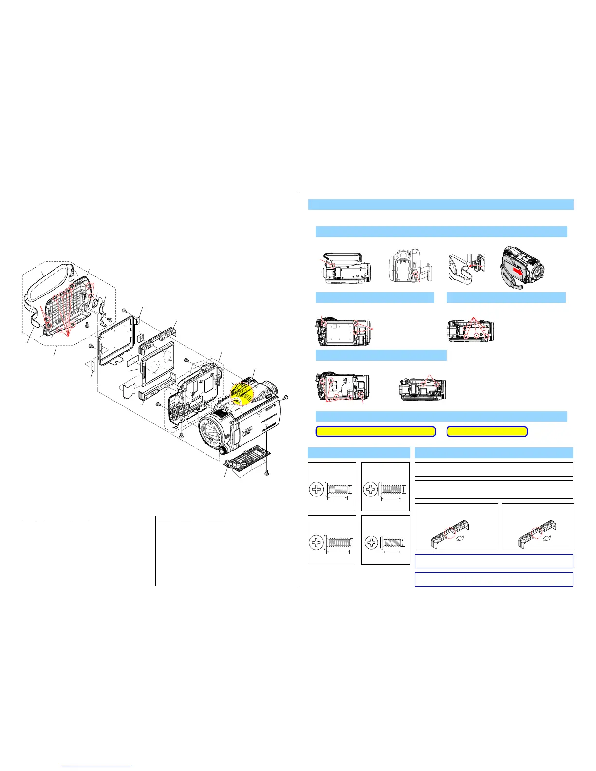
2-1. EXPLODED VIEWS
2-1-1. OVERALL SECTION-1
(XR550/XR550E/XR550V/XR550VE)
Refer to page 2-4 about CX550/CX550E/CX550V/CX550VE
ns: not supplied
Ref. No. Part No. Description
Ref. No. Part No. Description
1 X-2547-054-1 CABINET G (347) ASSY
2 2-664-928-41 BELT, GRIP
3 4-177-960-01 HEAT SINK G (347)
4 4-179-888-01 HD DAMPER SHEET
5 4-177-969-01 GASKET (10X10X4)
6 4-181-717-01 SHEET, HD GUARD
7 1-840-187-21 HDD (MK2431GAH-240GB) (XR550/XR550E)
7 A-1708-620-A SERVICE (240G_OPAL), HDD (XR550V/XR550VE)
(Note 1)
8 3-298-143-01 DAMPER (2), 08STYLE (Note 2)
9 X-2547-052-1 CABINET L (347) ASSY
10 2-589-376-01 FOOT (395), RUBBER
11 (Note 3) CABINET(BM)
#2 2-635-562-31 SCREW (M1.7)
#11 3-078-890-11 SCREW, TAPPING
#12 3-080-204-21 SCREW, TAPPING, P2
#158 2-660-401-51 SCREW (M1.7), NEW TRU-STAR, P2
1. Remove to numerical order (1 to 6) in the left figure.
DISASSEMBLY
8
(Note 2)
8
(Note 2)
10
4
4 11
(Note 3)
3 7
(Note 1)
Overall Section-2
(See page 2-5)
ns
ns
#12
ns
#11
#158
#2
#2
#2
#2
#2
#11
1 1
2 3
2
6
5 9
6
5
ns
1-1
1-2
(Claw)
(Claw)
(Claw)
1 #2 X 2 → Remove the Grip Belt (1-1) → Slide the Cabinet (G) Assy (1-2)
Screw
#2: M1.7 X 4.0
(Black)
2-635-562-31
4.0
1.7
Note
#2
Bottom View Back View
#2
2 #11 X 1 → #158 X 2
#158
#11
Left View
5 #12 X 1 → #2 X 6
#2
#2
#12
Left View Bottom View
#11: M1.7 X 4.0 (Tapping)
(Silver)
3-078-890-11
4.0
1.7
Note 2: In case of attaching, turn concave
portion to the main body side.
Main body
Concave Portion
Note 2:取付時は、窪みのある面を
本体側に向けて取り付けて
ください。
窪み
本体
Note 1: Do not factory check HDD in which Map Data is installed (XR550V/
XR550VE). The map data is erased when the factory check is done.
Note 1:
Note 3: Refer to page 1-4 “Precaution on replacing the Cabinet (BM)” when chang-
ing the Cabinet (BM).
Note 3:
4 #2 X 5
#2
Bottom View
DISCHARGING OF THE CHARGING CAPACITOR
6
#12: M1.7 X 5.0 (Tapping)
(Black)
3-080-204-21
1.7
5.0
5.0
1.7
#158: M1.7 X 5.0
(Red)
2-660-401-51
Refer to page 2-4 about CX550/CX550E/CX550V/CX550VE

 Loading...