1-2
HDR-CX550/CX550E/CX550V/CX550VE/XR550/XR550E/XR550V/XR550VE_L2
– ENGLISH –
1-5.
METHOD OF COPING WITH SHIFT LENS ERROR
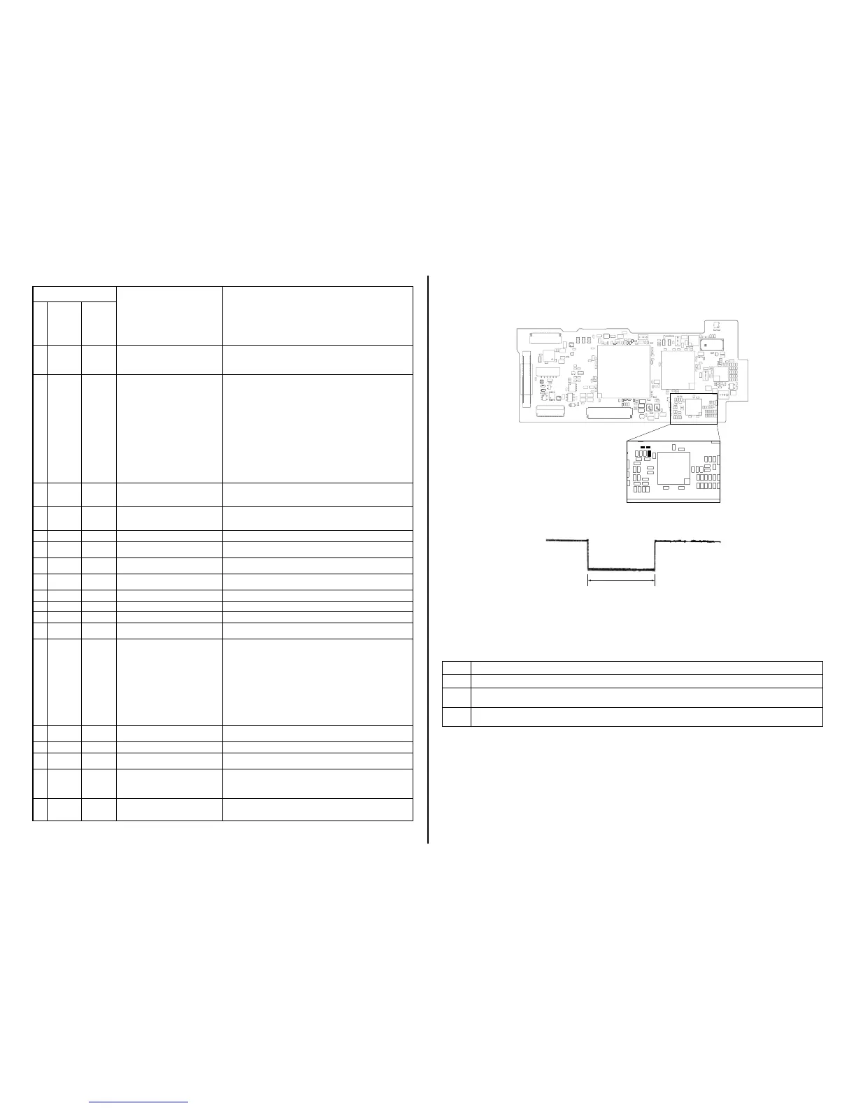
VC-592 BOARD (A SIDE)
IC5501
R5512
R5513
R5527
Fig. 1
Measurement points on the VC-592 board
about 330 msec
Note: The length of low section will vary a little depending on the conditions.
Fig. 2
Change in output voltage of R5513 on the VC-592 board
1-5-1. E : 62 : 02 [Abnormality of IC for Steadyshot] Occurred
Order Procedure
1 Turn the power OFF.
2
While measuring with an oscilloscope the output voltage of R5513 in the periphery of IC5501 on the VC-592 board, turn the
power ON to check that the output voltage immediately after the power on change as shown in Fig. 2.
3
If the output voltage change as shown in Fig. 2, replace the lens block (Note). If it does not change as shown in Fig. 2, inspect
the camera control circuit (IC7501 of VC-592 board) periphery.
Note: When the lens block was replaced, start the Adjust Manual in the Adjust Station and execute the necessary adjustment items.
After the adjustment, make sure with the STEADYSHOT turned ON that the steadyshot functions appropriately in the handheld operation.
Self-diagnosis Code
Symptom/State Correction
Repaired by:
Block
Function
Detailed
Code
E61 11
The abnormalities in initialization of
the focus lens and the abnormalities in
initialization of the zoom lens occurred
simultaneously.
Check both C: 32: 60 and E: 61: 10 of the self-diagnosis code.
E61 30
Reset position detection error on the
stepper iris initializing
Turn the power on to open lens barrier. Disconnect the battery or power cord,
and then connect again.
Confirm that the iris blades in lens are working.
If iris blades do not working, check the iris motor drive IC in lens drive block
(CN1001 pin qa to qf on VC-592 board).
If iris blades work normally, confirm that they are closing completely and
confirm following item.
• Case of the iris blades do not close normally
Replace the lens block (LSV-1390A (service)).
• Case of “E: 61: 30” is appeared and iris blades closed completely.
Confirm that communication with lens block is normal.
• Case of LCD is not displayed normally
Check that connection between CN6801 on CM-103 board and
CN1003 on VC-592 board by FP-1206 flexible board.
• Case of LCD is displayed normally
Replace the lens block (LSV-1390A (service)).
E62 00
Handshake correction function does not
work well. (With PITCH angular velocity
sensor output stopped.)
Inspect PITCH angular velocity sensors (SE9201 on the MM-094 board)
peripheral circuits.
E62 01
Handshake correction function does not
work well. (With YAW angular velocity
sensor output stopped.)
Inspect YAW angular velocity sensors (SE9201 on the MM-094 board)
peripheral circuits.
E 6 2 0 2 Abnormality of IC for steadyshot. Refer to [1-5-1. E : 62 : 02 (Abnormality of IC for Steadyshot) Occurred].
E62 03
IC for steadyshot and micro controller
communication abnormality among.
Inspect the steadyshot circuit (IC5501 on the VC-592 board).
E62 04
Image vibration correction during
handshake function does not work.
Inspect the image vibration angular velocity sensors
(SE9101 on VC-592 board) peripheral circuits.
E 6 2 1 0 Shift lens initializing failure.
Replacement of lens block. If an error occurs again, replace the VC-592
board. (Note2)
E 6 2 1 1 Shift lens overheating (Pitch) Refer to [1-5-2. E : 62 : 11 (Shift Lens Overheating (Pitch)) Occurred].
E 6 2 1 2 Shift lens overheating (Yaw) Refer to [1-5-3. E : 62 : 12 (Shift Lens Overheating (Yaw)) Occurred].
E 6 2 2 0 Abnormality of thermistor. Refer to [1-5-4. E : 62 : 20 (Abnormality of Thermistor) Occurred].
E91 01
Abnormality when flash is being
charged.
Checking of flash unit or replacement of flash unit.
E92 01
Battery current value goes over the max
discharge current
Check the remaining battery power because this symptom maybe depended
on the remaining battery level, and confirm whether or not the symptom is
occurred after replacing the battery. If the symptom is still occurred, over-
haul inspection is needed. Connect the MM-094 board with VC-592 board
through the FP-1198 (VC-MM) flexible board.
Connect the MM-094 board with Control Switch Block (PS34600/
PS34700).
VC-592 board connected to DD-329 board.
Check each output of DC/DC converter (IC4701) on DD-329 board with
connected the DC/Batt harness
(the minimum connection to periphery) to FP-1207 flexible board.
PS34600: XR550/XR550E/XR550V/XR550VE
PS34700: CX550/CX550E/CX550V/CX550VE
E94 00
Fault of writing or erasing the flash
memory
Inspect the flash memory (IC8101 on the VC-592 board).
E 9 4 0 1 Internal flash memory fault Inspect the flash memory (IC8101 on the VC-592 board).
E 9 4 0 2 BGM data error
Inspect the flash memory (IC8101 on the VC-592 board). If it is OK, check
the CPU (IC7501 on the VC-592 board).
E 9 5 0 0 GPS hardware error
CX550V/CX550VE/XR550V/XR550VE:
Check whether the flexible board of the GPS module is broken,and check
whether it is inserted imperfectly. If there is no problem the flexible board,
inspect or replacement of the GPS module.
E 9 6 0 0 Map area mount error
CX550V/CX550VE/XR550V/XR550VE:
Inspect or replacement of the DD-329 board (CX550V/CX550VE), hard
disk unit (XR550V/XR550VE).
Note2: When the lens block was replaced, start the Adjust Manual in the Adjust Station and execute the necessary adjustment items.
After the adjustment, make sure with the STEADYSHOT turned ON that the steadyshot functions appropriately in the handheld operation.
 Loading...