HBD-TZ215/TZ715
14
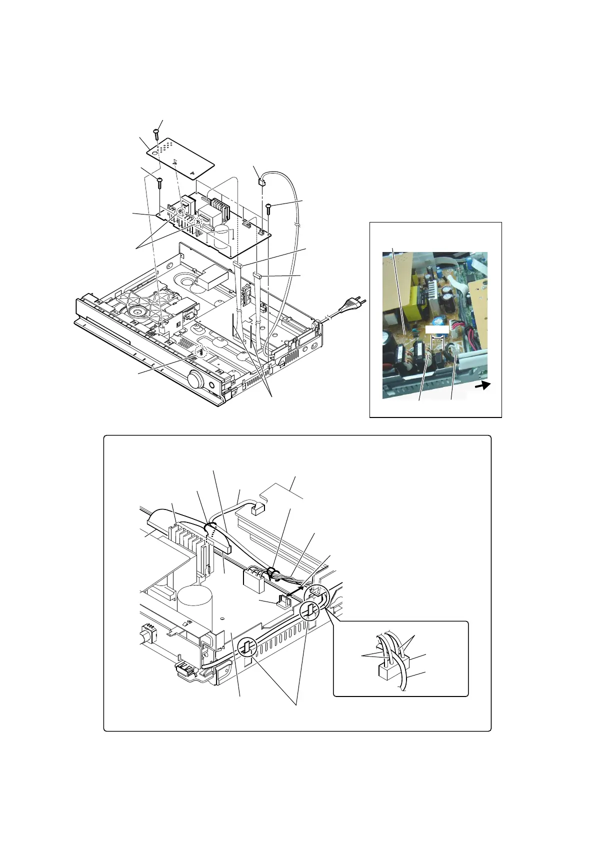
2-10. POWER BOARD
0 POWER board
6 two claws
8 four screws
(BV3 (3-CR))
8 four screws
(BV3 (3-CR))
5 screw
(BV3 (3-CR))
7 plate flow control (AMP)
9 holder PC board
1 power cord connector
(CN901)
3 connector
(CN904)
4 connector
(CN906)
2 Lift up two lead pins.
CN901
LF901
POWER board
3RZHUFRUGVHWWLQJ
6 mm
rear side
$UUDQJLQJWKH86%ZLUH
Have the USB wire spread on the inside
of the claws of the chassis.
USB wire
USB wire
heat sink
heat sink
CN3000
CN509
CN906
red
black
Tie up with LP3002.
Tie up with LP501.
Draw the USB wire through CN3000.
Keep a distance of more than 6.5 mm
between the wire and CN901.
Keep the wire tied up from lying on
the heat sink and the POWER board.
Keep the wire tied up from lying on
the heat sink and the POWER board.
POWER board
CN901
 Loading...