– 41 –
AM Tuned Level Adjustment
Band: AM or MW
Procedure:
1. Set the output of SSG so that the input level of the set be-
comes 55 dB.
2. Tune the set to 999 kHz.
3. Adjust RV41 to the point (moment) when the TUNED indica-
tor will change from going off to going on.
Adjustment Location : TCB board
FM Section Adjustment
Note: This adjustment should be performed after the AM Tuned
Level Adjustment due to the same adjustment element.
Setting:
FM Tuned Level Adjustment
Band: FM
Procedure:
1. Supply a 25dBµ 98 MHz signal from the ANTENNA termi-
nal.
2. Tune the set to 98 MHz.
3. If the TUNED indicator does not light, adjust RV42 to the
point (moment) when the TUNED indicator will change from
going off to going on.
Adjustment Location: TCB board
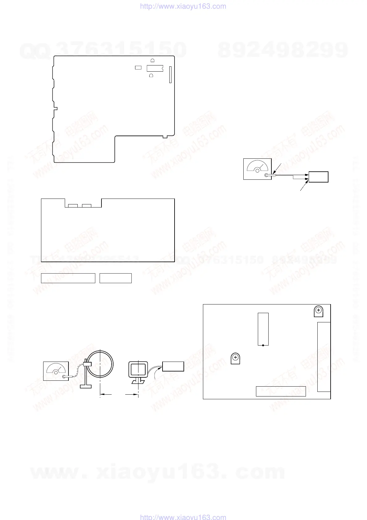
[TCB BOARD] (Component Side)
Carrier frequency : 98 MHz
Modulation : AUDIO 1 kH, 75 kHz
deviation (100%)
FM ANTENNA terminal
(TM1) (75
Ω
open)
75
Ω
coaxial
set
FM RF stereo signal
generator
RV42
IC41
RV41
TM1
FE1
[MAIN BOARD] (Component Side)
RV1501
CN207
IC1501
RV1551
CN205
[AUDIO BOARD] (Conductor Side)
RECORD
BAIS
TAPE SPEED
(NORMAL)
RV651
®
(HIGH)
RV652
®
RV311
L
®
RV411
R
®
PB
LEVEL
RV441 RV341
RV301
®
L
RV401
®
R
R
L
– DECK B –
– DECK A –
PB LEVEL
TUNER SECTION 0dB=1µV
(HCD-FR1: AEP, UK, German model only)
Note: As a front-end (FE1) is difficult to repair if faulty, replace
it with new one.
AM Section Adjustment
Setting:
AM RF signal
generator
loop antenna A
set
loop antenna B
60 cm
AM ANTENNA
terminal (TM1)
30% amplitude
modulation by
400 Hz signal
w
w
w
.
x
i
a
o
y
u
1
6
3
.
c
o
m
Q
Q
3
7
6
3
1
5
1
5
0
9
9
2
8
9
4
2
9
8
T
E
L
1
3
9
4
2
2
9
6
5
1
3
9
9
2
8
9
4
2
9
8
0
5
1
5
1
3
6
7
3
Q
Q
TEL 13942296513 QQ 376315150 892498299
TEL 13942296513 QQ 376315150 892498299
http://www.xiaoyu163.com
http://www.xiaoyu163.com
 Loading...