Do you have a question about the Sony ICF-SW100 and is the answer not in the manual?
Details the frequency coverage for FM, SW, MW, and LW bands.
Provides physical size and weight specifications of the unit.
Lists the items included with the ICF-SW100S and ICF-SW100E.
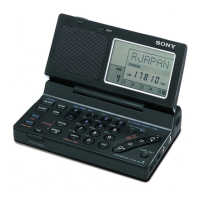
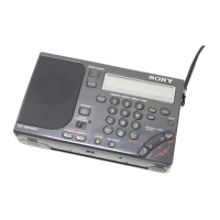
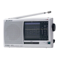
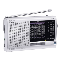
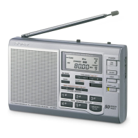
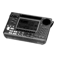
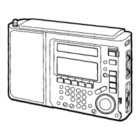
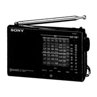
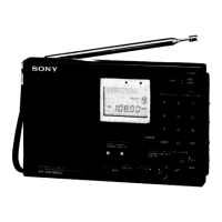
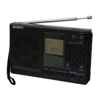
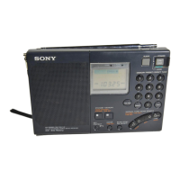
Identifies and describes controls on the front and rear panels.
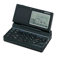
Explains the meaning of various symbols and indicators on the display.
Details the function of each button on the control panel.
Lists time differences between various locations and UTC.
Describes how to check the time in different world locations.
Explains how to tune to pre-saved stations using memory pages.
Instructions for tuning directly by entering the frequency.
Guide for tuning stations manually using frequency steps.
How to automatically scan for broadcast stations within a band.
Steps to store favorite stations into memory for quick access.
How to customize labels for preset stations or time zones.
Instructions for setting the radio to turn on or off automatically.
How to set the radio to turn off automatically after a set time.
Advice for improving reception, including antenna usage.
Procedure for disassembling the rear cabinet or lid of the unit.
Steps for accessing and removing the main chassis of the unit.
Details adjustments for the AM tuning and reception circuits.
Procedure for adjusting the first intermediate frequency stage.
Adjusting the VCO voltage for FM frequency range coverage.
Fine-tuning the FM circuit for optimal tracking across frequencies.
Adjusting the FM stereo reception circuit for clarity.
Adjustment related to the signal detection circuit.
Setting the zero beat for Single Side Band reception.
Pin assignments for key integrated circuits in the synthesizer control.
High-level overview of the radio's functional blocks and interconnections.
Visual guides showing the pin configurations of semiconductor components.
Circuit diagram for the AN-100 active antenna section.
Layout of the printed circuit board for the AN-100 active antenna.
Component placement on the tuner section's printed circuit board.
Circuit diagram detailing the tuner section's electronic components.
Circuit diagram for the radio's control and microcomputer sections.
Component layout on the control section's printed circuit board.
Exploded view showing the assembly of the radio's main body.
Exploded view illustrating the assembly of the AN-100 active antenna.
List of electrical parts used in the active antenna.
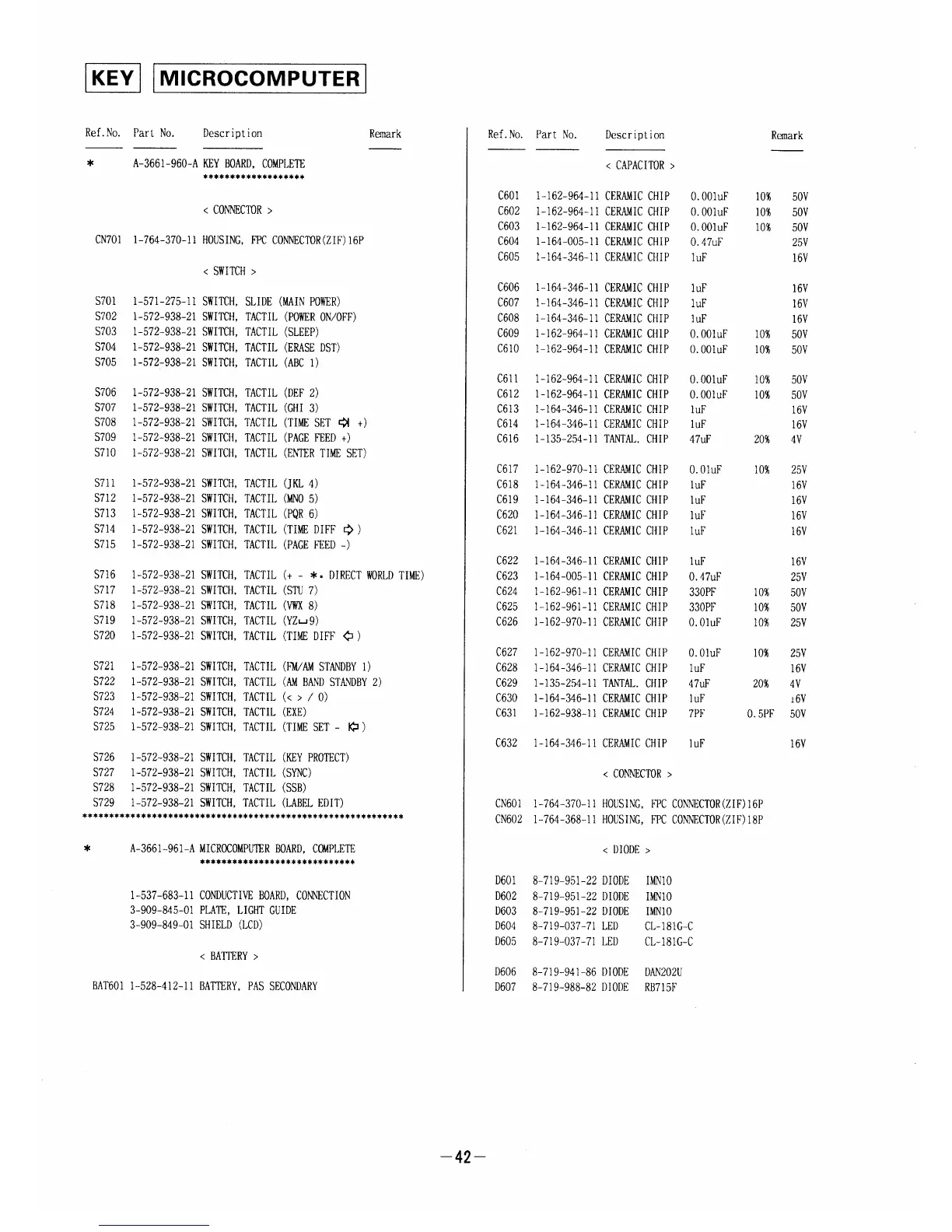
List of electrical components for the key input board.
List of electrical parts for the microcomputer board.
List of electrical components for the signal board.
Lists other parts like PC boards, cords, and speakers.
Details the various accessories supplied with the radio.
Information on changes to the Key, Microcomputer, and Signal boards.
Details the change in the microcomputer IC102 and related components.