– 14 –
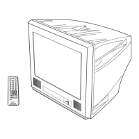
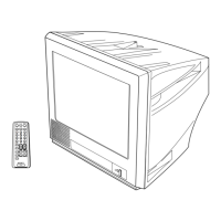
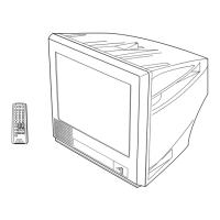
KV-PG14M40/PG14M72/L/N
KV-PG14P42/G/L/N/PG14P70
RM-952
The following adjustments should be made when a complete
realignment is required or a new picture tube is installed.
These adjustments should be performed with rated power
supply voltage unless otherwise noted.
Controls and switches should be set as follows unless otherwise
noted:
PICTURE control ........................................................... normal
BRIGHTNESS control................................................... normal
Perform the adjustments in the following order :
1. Beam Landing
2. Convergence
3. Focus
4. White Balance
Note : Test Equipment Required.
1. Pattern Generator
2. Degausser
3. Oscilloscope
SECTION 3
SET-UP ADJUSTMENTS
................................................................................................................................................................................................................................
normal
Preparation :
In order to reduce the influence of geomagnetism on the
set's picture tube, face it east or west.
Switch on the set's power and degauss with the degausser.
3-1. BEAM LANDING
1. Input a white signal with the pattern generator.
Contrast
Brightness
2. Set the pattern generator raster signal to a green raster.
3. Move the deflection yoke to the rear and adjust with the
purity control so that the green is at the center and the blue
and the red take up equally sized areas on each side.
(See Figures 3-1 through 3-4.)
4. Move the deflection yoke forward and adjust so that the
entire screen is green. (See Figure 3-1.)
5. Switch the raster signal to blue, then to red and verify the
condition.
6. When the position of the deflection yoke has been decided,
fasten the deflection yoke with the screws and DY spacers.
7. If the beam does not land correctly in all the corners, use a
magnet to adjust it.
(See Figure 3-4.)
}
Fig. 3-1
Fig. 3-4
Fig. 3-3
Fig. 3-2
Purity control
Red
Blue
Green
Purity control
corrects this area.
Disk magnets or rotatable
disk magnets correct these
areas (a-d).
Deflection yoke positioning
corrects these areas.
a
b
c
d
b
c
d
a
 Loading...