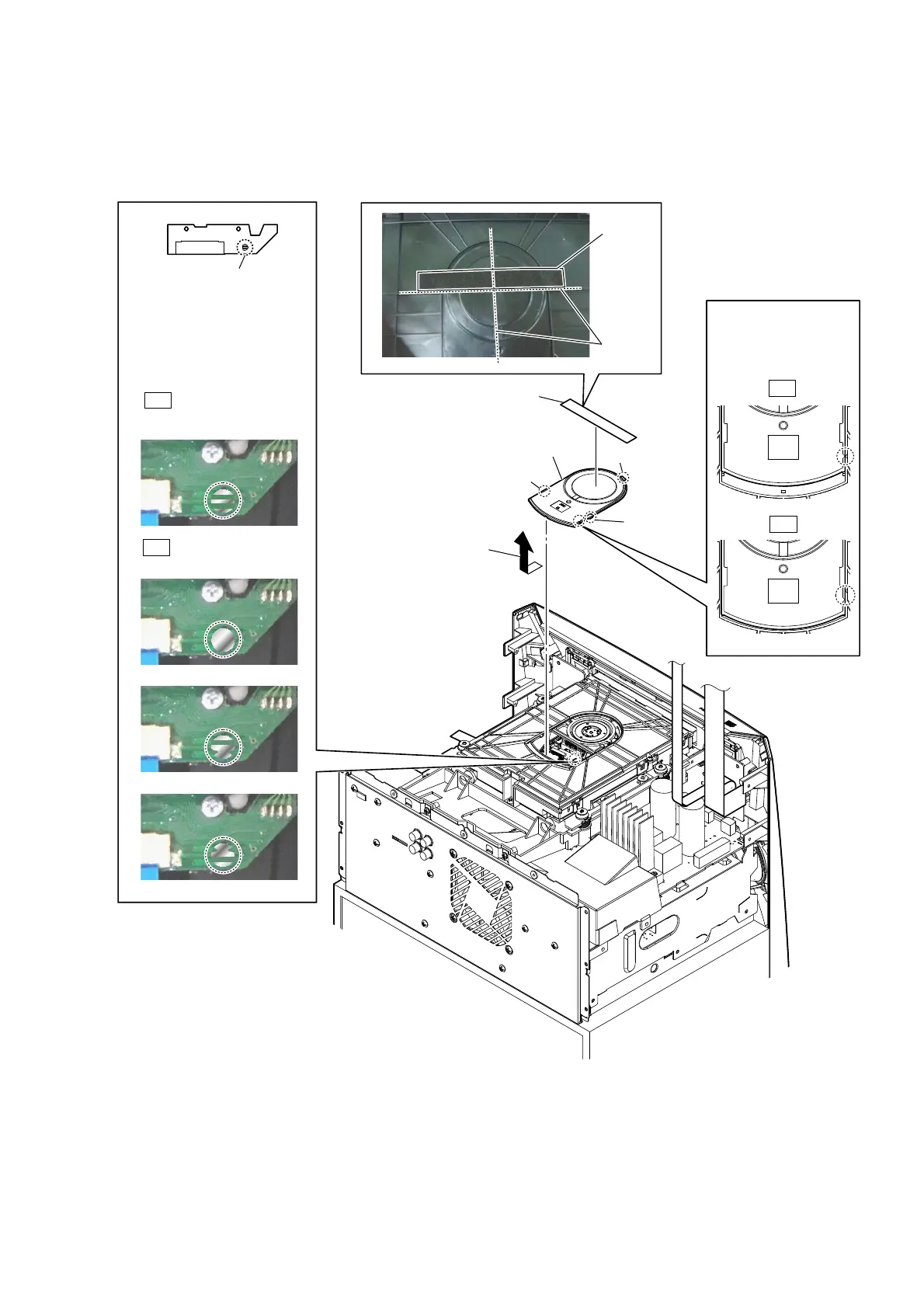
EasyManuals Logo
Home>Sony>Stereo System>MHC-V5

Sony MHC-V5 Service Manual

Sony MHC-V5
102 pages
To Next Page IconTo Next Page
To Previous Page IconTo Previous Page
Page #11 background imageLoading...
Page #11 background image
MHC-V5
11
2-5. CDM BLOCK-1
Continued on 2-6 (page 12).
Note 1: Before disconnecting exible at cable (24P) (CN302), solder the short-land.
– Top rear view –
3 Remove the chuck cap
in the direction
of the arrow.
4 chuck cap
2 claw
2 claw
2 claw
Note 3:
When installing
the chuck cap,
align the triangle
marks.
OK
NG
5
Solder the short-land.
Note 2: When assembling the CDM
block, remove the solder of
short-land after connecting
flexible flat cable (24P)
(CN302).
Solder is removed cleanly.
Solder is not removed.
OK
NG
1 cushion (E)
cushion (E)
guide line

Table of Contents

Other manuals for Sony MHC-V5

Questions and Answers:

Question and Answer IconNeed help?

Do you have a question about the Sony MHC-V5 and is the answer not in the manual?

Sony MHC-V5 Specifications

General IconGeneral
On/off switchYes
Product colorBlack
Recommended usageUniversal
Suitable for outdoor use-
Speaker type3-way
Driver diameter250 mm
Speaker positionFront
Tweeter diameter40 mm
Number of drivers3
Speaker placementFloor
Audio output channels1.0 channels
Mid-range driver diameter100 mm
Number of tweeter drivers1
Recommended amplifier power (max)240 W
Recommended amplifier power (min)0.5 W
Impedance5 Ω
Frequency range- Hz
RMS rated power1440 W
Peak Music Power Output (PMPO)15840 W
Number of amplifier channels2 channels
Power source typeAC
USB 2.0 ports quantity2
Connectivity technologyWired & Wireless
AC input voltage120 V
AC input frequency60 Hz
TypeHome audio mini system
Weight and Dimensions IconWeight and Dimensions
Depth325 mm
Width339 mm
Height908 mm
Weight18000 g

Related product manuals