MHC-V5
MHC-V5
3737
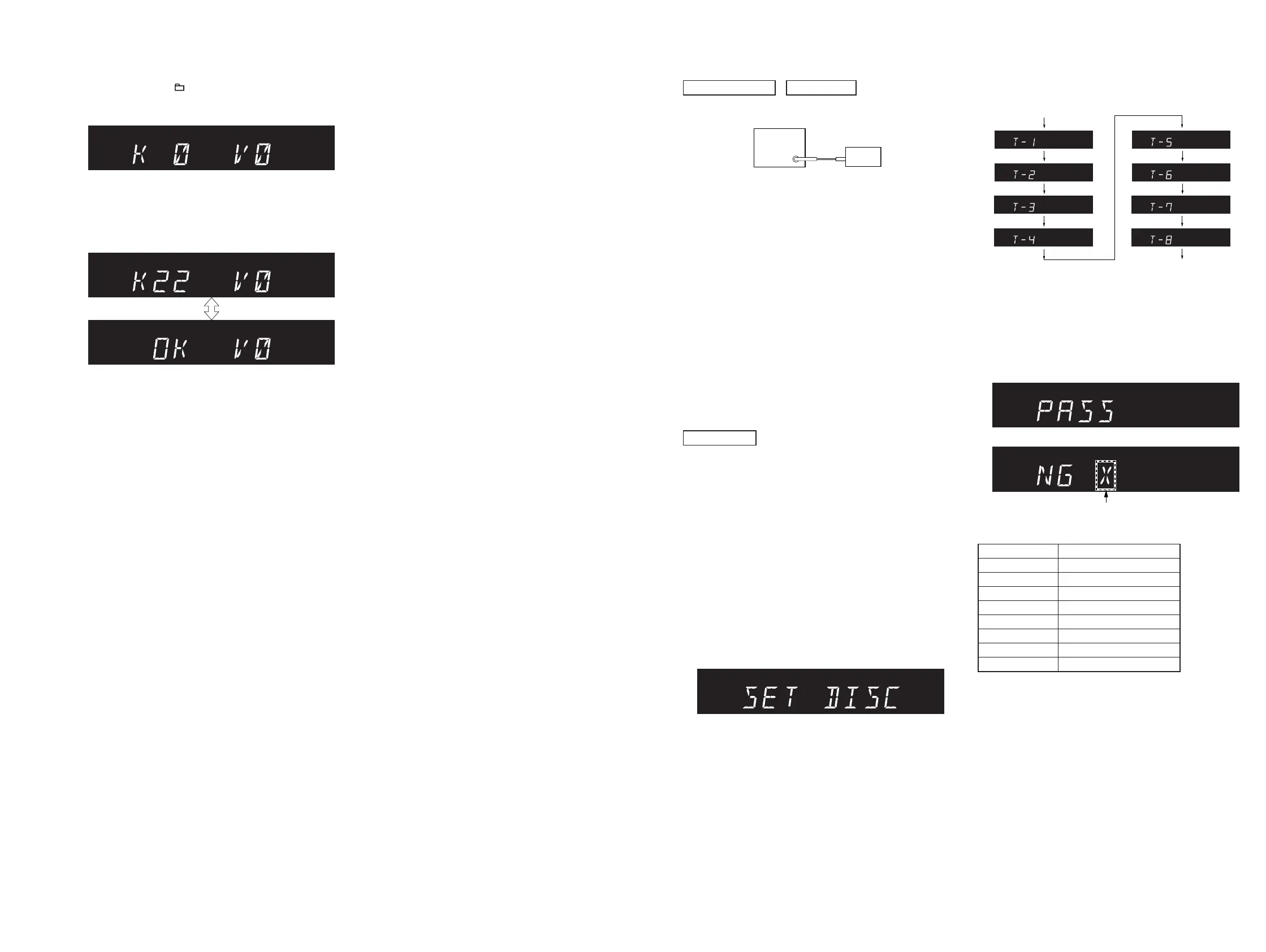
8. When pressing the [ –] button, “K 0 V0” is displayed on the
fl uorescent indicator tube.
Screen display
9. Each time a button is pressed, “K 0” value increases. However,
once a button is pressed, it is no longer taken into account.
When pressing the all buttons, “K22” and “OK” are displayed
alternately
Screen display
10. “V0” value increases “V1”, “V2”, “V3” · · · “V8”, “V9”, “V0”
if turn the [VOLUME/DJ CONTROL] knob clockwise, or it
decreases “V9”, “V8”, “V7” · · · “V2”, “V1”, “V0” if turn the
knob counterclockwise.
Releasing method:
Press two buttons of the [ENTER] and [FOOTBALL] simultane-
ously for three seconds.
SECTION 4
ELECTRICAL CHECKS
TUNER SECTION
0 dB = 1 V
FM TUNE LEVEL CHECK
signal
generator
unit
Procedure:
1. Press the [
?
/
1
] button to turn the power on.
2. Input the following signal from signal generator to FM antenna
input directly.
Carrier frequency : A = 87.5 MHz, B = 98 MHz, C = 108 MHz
Deviation : 75 kHz
Modulation : 1 kHz
ANT input : 35 dBu (EMF)
Note: Use 75 ohm coaxial cable to connect signal generator and the unit.
You cannot use video cable for checking.
Use signal generator whose output impedance is 75 ohm.
3. Set to FM tuner function and tune A, B and C signals.
4. Confi rm “TUNED” is lit on the display for A, B and C signals.
When the selected station signal is received in good condition,
“TUNED” is displayed.
CD SECTION
Note:
1. CD block is basically constructed to operate without adjustment.
2. Use HLX-A1 disc (Part No. J-2501-307-A) unless otherwise indicat-
ed.
3. Clean the object lens by an applicator with lens cleaning liquid when
the servo check result is “NG”.
SERVO CHECK
Procedure:
1. Press the [
?
/
1
] button to turn the power on.
2. Press the [FUNCTION] button to turn the CD function.
3. Press two buttons of the [FOOTBALL] and [PAN] simultane-
ously for three seconds.
4. Check that “SET DISC” is displayed on the fl uorescent indica-
tor tube. And test disc (HLX-A1) is set after a disc tray opens
automatically.
Screen display
5. Press the [
Z
] button to close the disc tray.
6. Servo check is started, following screen is displayed on the
fl uorescent indicator tube.
Servo check start
Servo check end
7. Waits to complete a servo check and for a disc tray to open
automatically.
8. Test disc (HLX-A1) is taken out, and press the [Z] button to
close the disc tray.
9. “PASS” or “NG X” (X: error No. (1 to 8)) is displayed on the
fl uorescent indicator tube.
Screen display
or
Error No. (1 to 8)
Servo check item:
Error No. Servo check item
1 Disc Type
2 SPFG (No check)
3 Mirror Time
4 TE Level
5 S Level
6 S Balance
7 RF Level
8 Jitter
Releasing method:
Press two buttons of the [FOOTBALL] and [PAN] simultaneously
for three seconds.

 Loading...